Liquid Ejection Head And Driving Method Thereof

Active Publication Date: 2008-04-10
BROTHER KOGYO KK +1
View PDF3 Cites 13 Cited by
  • Summary
  • Abstract
  • Description
  • Claims
  • Application Information

AI Technical Summary

Benefits of technology

[0017] According to the above aspect, the liquid ejection head is driven under the condition that either of Tr/Tc2 and Tf/Tc2 is substantially not less than 0.3 and not m

Problems solved by technology

In some cases, however, designing so that such a proper oscillation is not generated impairs efficient ink ejection, which is a merit of the fill-before-fire method.
In addition, a liquid ejection head in which such a shorter-period proper oscillation is not generated

Method used


Image

  • Liquid Ejection Head And Driving Method Thereof
  • Liquid Ejection Head And Driving Method Thereof
  • Liquid Ejection Head And Driving Method Thereof

Examples


Embodiment Construction

[0042] Hereinafter will be described a preferred embodiment of the present invention.

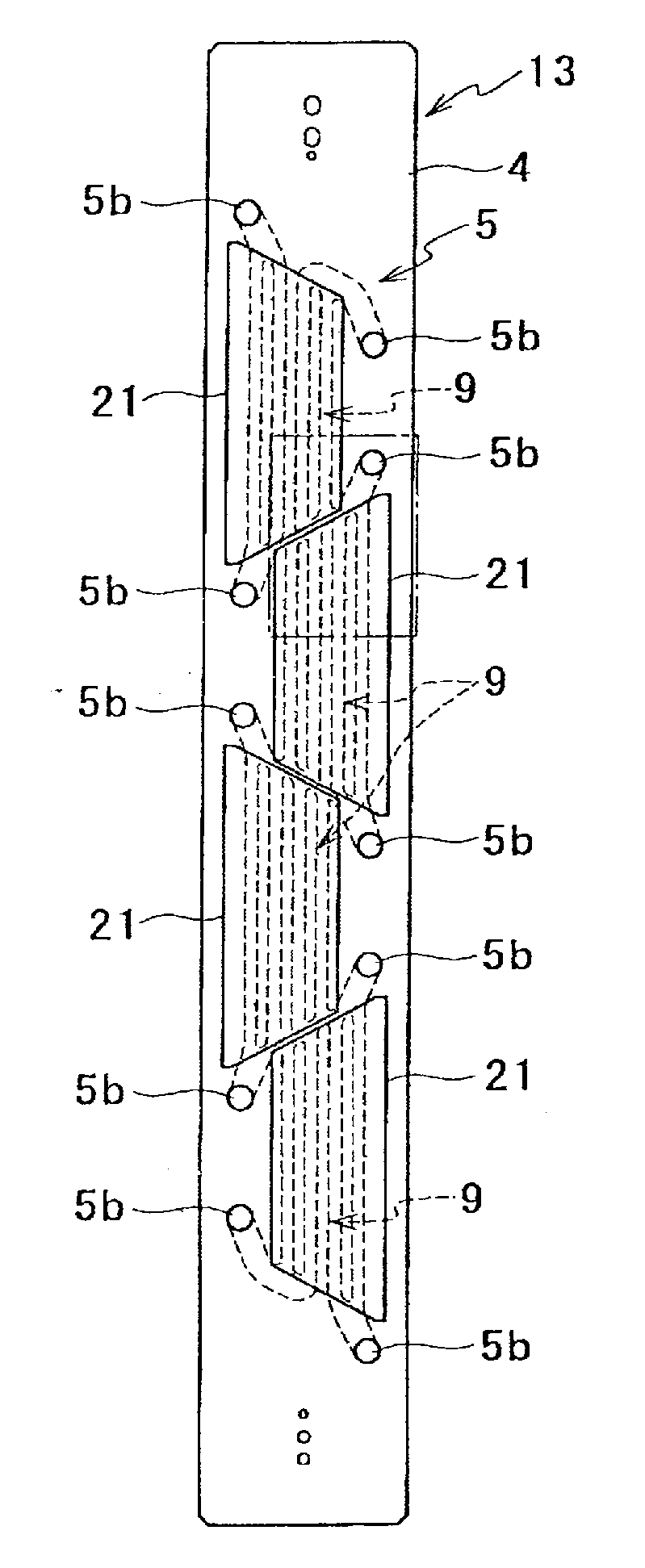
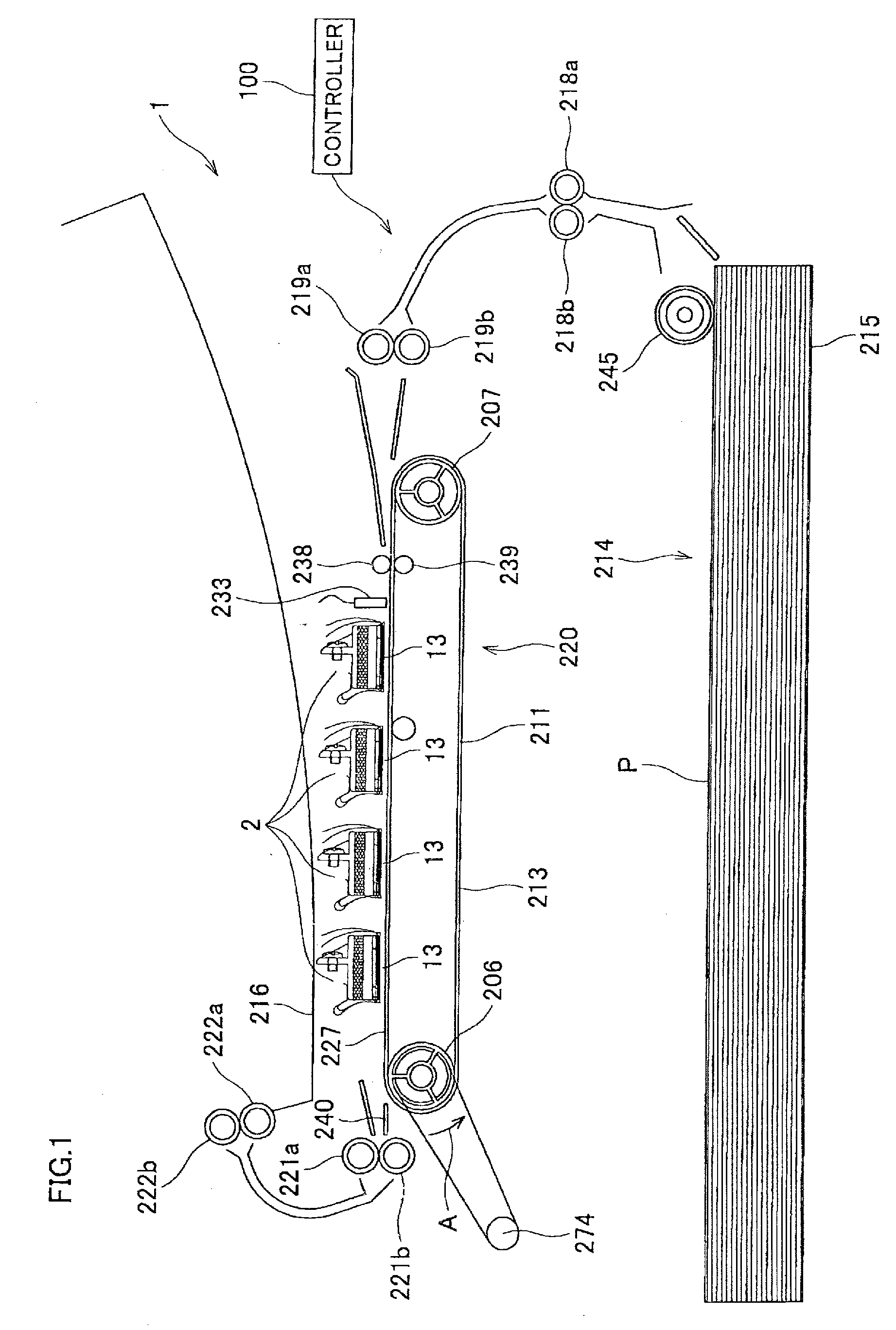
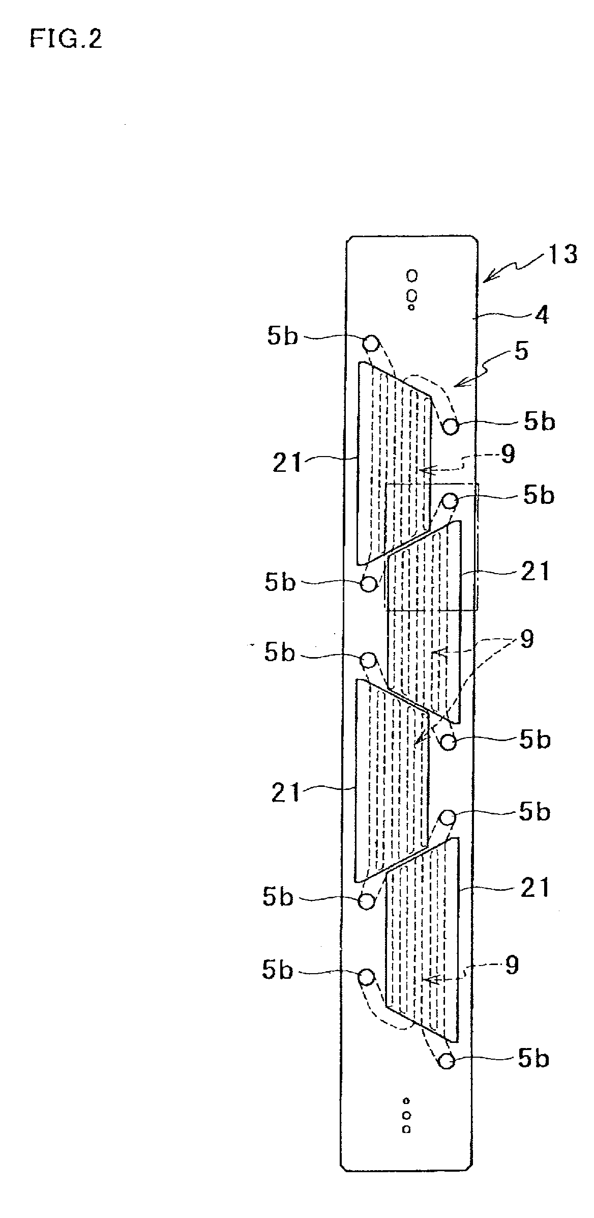
[0043]FIG. 1 shows a general construction of a color inkjet printer according to an embodiment of the present invention. The printer 1 includes therein four inkjet heads 2. The inkjet heads 2 are fixed to the printer 1 in a state of being arranged in the direction of conveyance of printing papers P. Each inkjet head 2 has a slender profile extending perpendicularly to FIG. 1.

[0044] The printer 1 includes therein a paper feed unit 214, a conveyance unit 220, and a paper receiving unit 216 provided in this order along the conveyance path for printing papers P. The printer 1 further includes therein a controller 100 that controls the operations of components and units of the printer 1, such as the inkjet heads 2 and the paper feed unit 214.

[0045] The paper feed unit 214 includes a paper case 215 and a paper feed roller 245. The paper case 215 can contain a number of printing papers P. The paper feed...


PUM


Abstract

A liquid ejection head includes a passage unit and an actuator. A nozzle for ejecting liquid and a common liquid chamber are formed in the passage unit. An individual liquid passage formed in the passage unit includes a first passage a pressure chamber, a second passage, and a restricted passage. The first passage communicates between the nozzle and the pressure chamber. The second passage communicates between the pressure chamber and the restricted passage. The restricted passage is smaller than the second passage in the sectional area perpendicular to the flow of the liquid. The actuator can selectively take a first state in which the volume of the pressure chamber is V1 and a second state in which the volume of the pressure chamber is V2 larger than V1. The actuator changes from the first state into the second state and then returns to the first state to eject the liquid from the nozzle. The individual liquid passage is designed so that Tc1 and Tc2 defined by predetermined expressions showing characteristics of the individual liquid passage satisfy a condition that Tc1/Tc2 is substantially not less than 4.7 and not more than 5.5.

Description

[0001] The present application claims priority from Japanese Patent Application No. 2006-249775, which was filed on Sep. 14, 2006, the disclosure of which is herein incorporated by reference in its entirety. BACKGROUND OF THE INVENTION [0002] 1. Field of the Invention [0003] The present invention relates to a liquid ejection head, in particular, adopting a so-called fill-before-fire method for ejecting liquid, and also to a driving method of the head. [0004] 2. Description of Related Art [0005] A liquid ejection head typified by an inkjet head adopting an inkjet system has a passage unit on which nozzles are formed for ejecting liquid, as disclosed in Japanese Patent Unexamined Publication No. 2003-39673. In the passage unit of the liquid ejection head, there are formed common liquid chambers for supplying liquid to the nozzles; and individual liquid passages leading from the common liquid chambers to the respective nozzles. A pressure chamber is formed in the middle of each individ...

Claims


Application Information

Patent Timeline
IPC IPC(8): B41J2/045
CPCB41J2/04581B41J2/04588B41J2/14209B41J2202/20B41J2002/14225B41J2002/14306B41J2002/14459B41J2002/14217
Inventor HIBI, MANABUIWAO, NAOTOISHIKURA, SHIN
Owner BROTHER KOGYO KK
Why Eureka
Try Eureka