Electrical connector structure

a technology of electrical connectors and connectors, applied in the direction of electrical apparatus, connection, coupling device connection, etc., can solve the problems of prior art connectors easily rocking on circuit boards, terminals of connectors easily deformation or breakage, etc., to achieve the effect of optimum electric conducting effectiveness, improved connector structure, and increased positioning strength

Inactive Publication Date: 2008-04-10
SINGATRON TECH HONG KONG CO
View PDF5 Cites 1 Cited by
  • Summary
  • Abstract
  • Description
  • Claims
  • Application Information

AI Technical Summary

Benefits of technology

[0005]The present invention relates to an improved connector structure, and more particularly to a connector able to use a conducting body to fasten to a circuit board, and which utilizes the function of fastening members to increase positioning strength, thereby enabling the connector to be firmly positioned on the circuit board, and achieve optimum electric conducting effectiveness.

Problems solved by technology

1. Lacks disposition of fastening devices, thereby resulting in the connector of prior art easily rocking on a circuit board.
3. Shortcoming 2 causes troublesomeness in that terminals of the connector easily deform or break.

Method used


Image

  • Electrical connector structure
  • Electrical connector structure
  • Electrical connector structure

Examples


Embodiment Construction

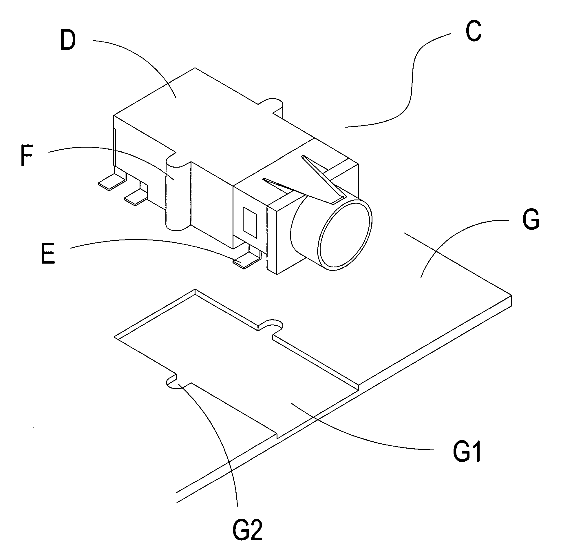
[0012]Referring to FIGS. 3 and 4, which show an improved connector structure of the present invention, wherein a connector C is primarily structured to comprise a conducting body D, electric conducting terminals E and fastening members F. A plurality of holes D1 are defined in the conducting body D, and the electric conducting terminals E are respectively located to correspond to the holes D1, thereby enabling the electric conducting terminals E to respectively penetrate the holes D1. Furthermore, when an electrical connection is made to a corresponding containing hole D2 of the conducting body D, then the holes D1 enable an electrical connection to be made to the electric conducting terminals E.

[0013]A plurality of mutually corresponding fastening members F extend from the conducting body D, and when the connector C is connected, the fastening members F provide a function to strengthen position fixing of the conducting body D, thereby achieving the objective of effecting a firm fas...


PUM


Abstract

The present invention provides an improved connector structure in which a connector is structured from a conducting body, electric conducting terminals and fastening members, wherein terminals, which electrically connect with a circuit and connecting terminals, are disposed interior of the conducting body. The fastening members extend from the conducting body, and the fastening members enable the conducting body to embed into a circuit board, thereby enabling the connector to fasten into corresponding holes of the circuit board by means of the fastening members, and thus achieve the objective of increasing positioning strength.

Description

BACKGROUND OF THE INVENTION[0001](a) Field of the Invention[0002]The present invention relates to an improved connector structure, and more particularly to a connector able to use a conducting body to fasten to a circuit board, and which utilizes the function of fastening members to increase positioning strength.[0003](b) Description of the Prior Art[0004]Referring to FIGS. 1 and 2, which show a connector A of prior art, wherein the connector A is fitted to a circuit board B for use thereof, but lacks disposition of fastening devices, and merely uses terminals A1 of the connector A to connect to the circuit board by a soldering method. However, the soldering method easily results in the connector A rocking on the circuit board B when in use, which, after using for a long period of time, easily bringing about deformation or breaking of the terminals A1 of the connector A, thereby leading to concern over damage to the connector A or the terminals A1 coming loose. Hence, the inventor o...

Claims


Application Information

Patent Timeline
Patent Type & Authority Applications(United States)
IPC IPC(8): H01R13/66
CPCH01R12/7052H01R12/727H01R12/707
Inventor HONG, SIOU-YILIU, LUN-TING
Owner SINGATRON TECH HONG KONG CO
Why Eureka
Try Eureka