Continuously adaptive fastener clip

Active Publication Date: 2008-04-17
TERMAX CORP
View PDF29 Cites 36 Cited by
  • Summary
  • Abstract
  • Description
  • Claims
  • Application Information

AI Technical Summary

Problems solved by technology

However, these conventional fastener devices instead provide approximately relatively equal levels of insertion and extraction force.
Conventional fastener devices typically do not adequately fasten to a range of sheet metal thicknesses and do not minimize or eliminate buzzing and rattling and do not sufficiently accommodate variations in production tolerances.
Further, each step has a relatively large rise and run so that, once inserted, movement of the fastener clip within the range of a step size may occur, resulting in wear and/or the generation of noise, including buzzing and

Method used


Image

  • Continuously adaptive fastener clip
  • Continuously adaptive fastener clip
  • Continuously adaptive fastener clip

Examples


Embodiment Construction

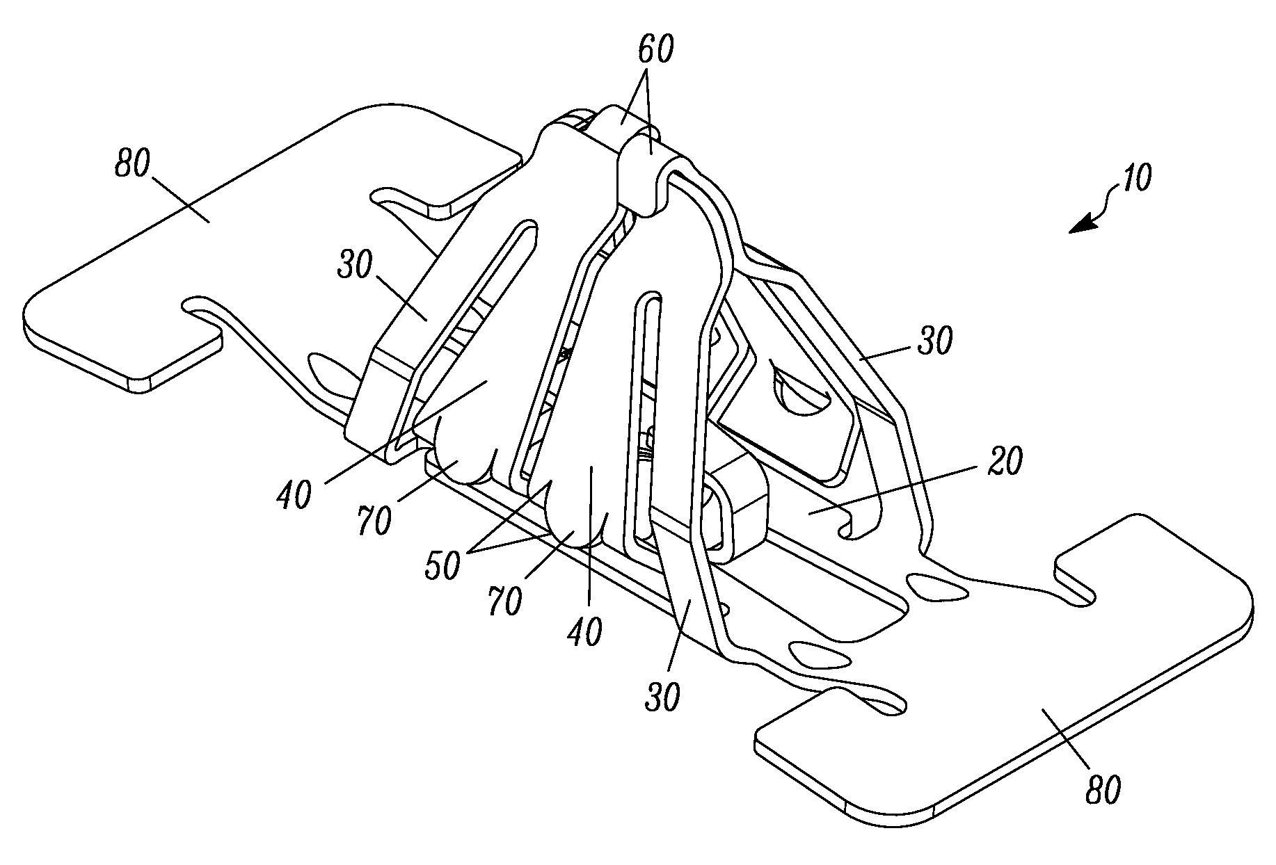
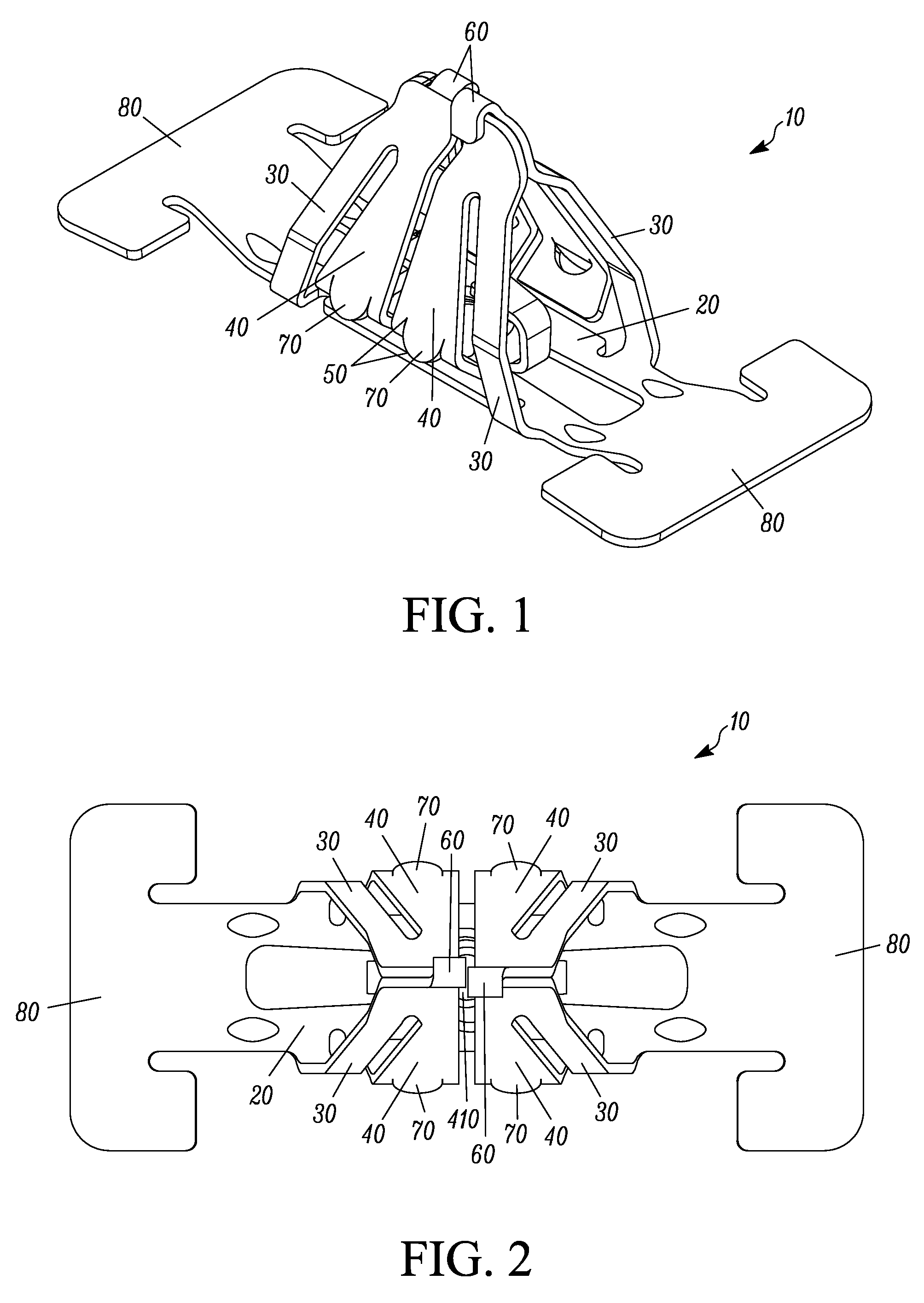
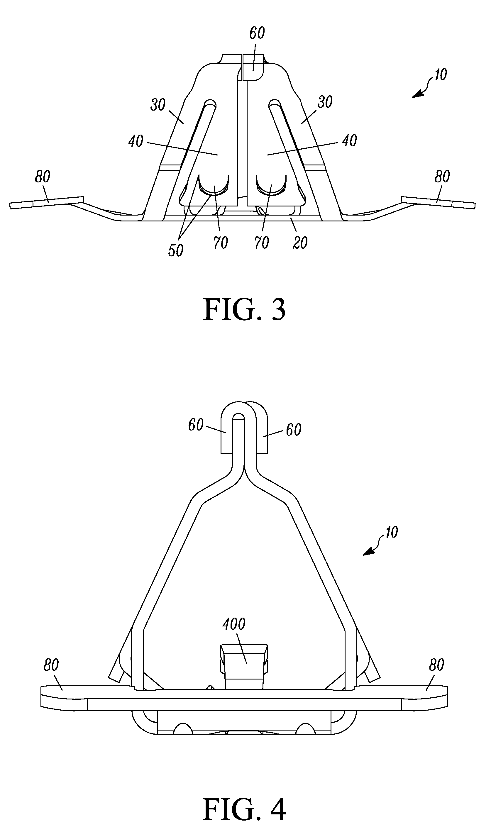
[0017] A fastener clip includes a base plate and a first and second pair of laterally offset legs extending from the base plate. At least one first wing extends from the first pair of laterally offset legs. The at least one first wing has an engagement region. At least one second wing extends from the second pair of laterally offset legs. The at least one second wing has an engagement region. The fastener clip adapts to different frame thicknesses such that a distance between the engagement regions and the base plate or frame is operative to vary continuously according to a slot thickness. The range of slot thicknesses varies continuously from a minimum thickness to a maximum thickness. For example, the minimum thickness may be 0.25 mm or less and the maximum thickness may be 6.0 mm or more. The fastener clip is operative for insertion into the slot defined in a first engagement structure, such as a vehicle chassis.

[0018] Among other advantages, the fastener clip relatively easily ...


PUM


Abstract

A fastener clip includes a base plate and a first and second pair of laterally offset legs extending from the base plate. At least one first wing extends from the first pair of laterally offset legs. The at least one first wing has an engagement region. At least one second wing extending from the second pair of laterally offset legs. The at least one second wing has an engagement region, such that a distance between the engagement regions and the base plate is operative to vary continuously according to a slot thickness. The fastener clip is operative for insertion into the slot defined in a first engagement structure, such as a vehicle chassis.

Description

RELATED APPLICATIONS [0001] This is a continuation in part application claiming priority from an application entitled “Multicontact Adaptive Fastener Clip” having a docket number P042 (04.0002) and a Ser. No. 11 / 277,107, having a filing date of Mar. 21, 2006, which is a continuation in part of U.S. patent application Ser. No. 10 / 906,209 having a docket number P041 (04.001) filed on Feb. 9, 2005, the entire disclosure of which is incorporated herein by reference all of which are incorporated herein by reference in their entirety.FIELD OF THE INVENTION [0002] The invention relates generally to devices for fastening objects, and more particularly to a fastener clip for insertion into an engagement structure, such as a vehicle chassis, a hollow substrate, a wall, a plate or any suitable surface. BACKGROUND OF THE INVENTION [0003] A number of devices and fasteners are currently available for fastening panels, such as body panels and automobile interior trimpiece panels, to the chassis of...

Claims


Application Information

Patent Timeline
IPC IPC(8): F16B5/06
CPCB60R13/0206B60R13/04Y10T24/30F16B21/076Y10T24/44026F16B21/075Y10T24/304Y10T24/306Y10T24/307
Inventor SMITH, MICHAEL WALTERDICKINSON, DANIEL JAMES
Owner TERMAX CORP
Why Eureka
Try Eureka