

Zoom lens and imaging system using the same
a technology applied in the field of zoom lens and imaging system, can solve the problems of inability to thin the zoom lens received at the lens mount, unfit for slimming down a camera, long length, etc., and achieve the effect of easy correction of field curvature and chromatic aberration of magnification
- Summary
- Abstract
- Description
- Claims
- Application Information
AI Technical Summary
Benefits of technology
Problems solved by technology
Method used
Image

Examples
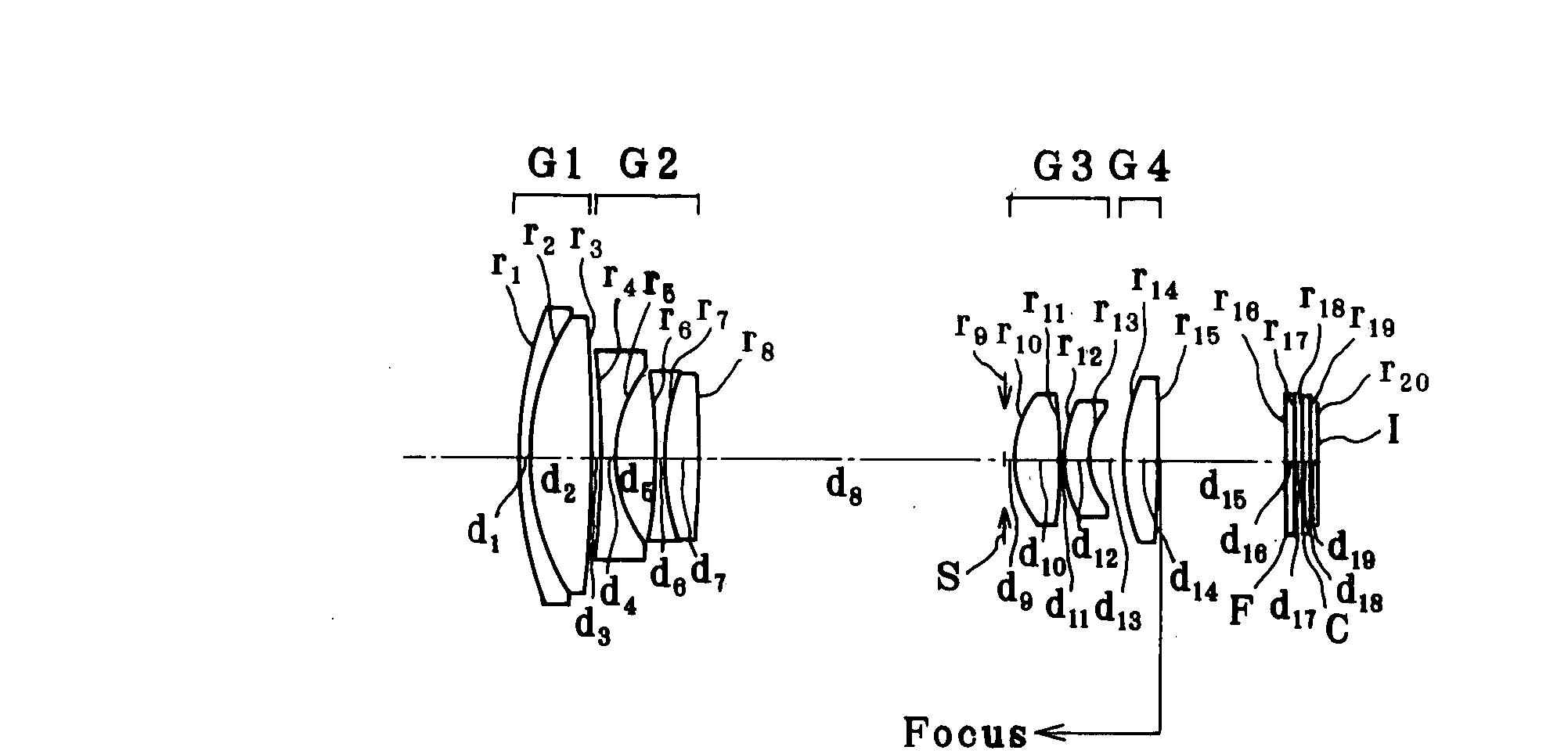
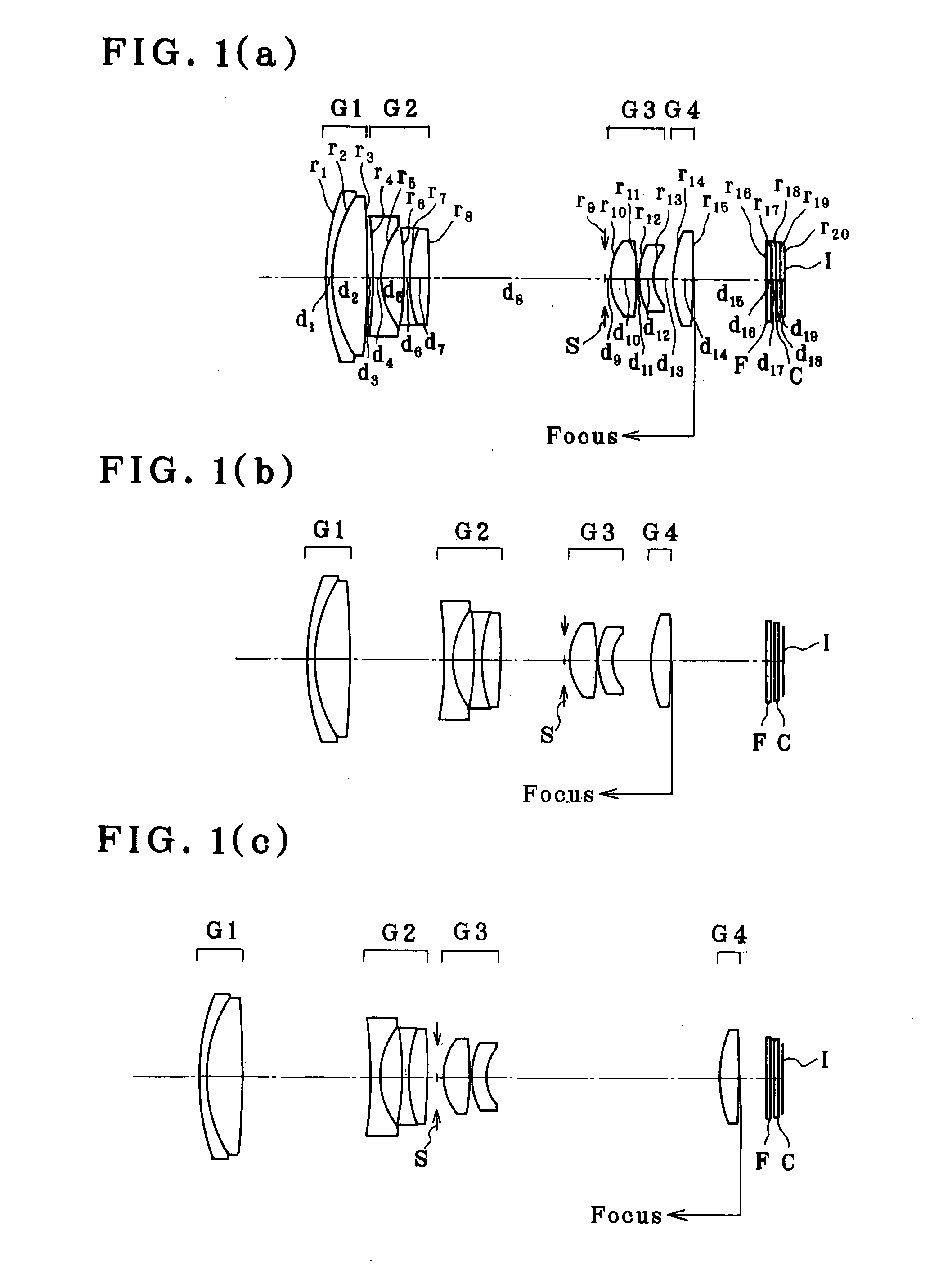
example 1
[0124]
r1 = 26.441d1 = 1.00nd1 = 2.00170νd1 = 20.64r2 = 17.392d2 = 3.95nd2 = 1.76802νd2 = 49.24r3 = −99.096d3 = (Variable)(Aspheric)r4 = −191.773d4 = 1.00nd3 = 1.88300νd3 = 40.76(Aspheric)r5 = 9.192 (Aspheric)d5 = 2.50r6 = −22.216d6 = 0.80nd4 = 1.88300νd4 = 40.76(Aspheric)r7 = 15.409d7 = 2.25nd5 = 2.00170νd5 = 20.64r8 = −56.881d8 = (Variable)r9 = ∞ (Stop)d9 = 0.50r10 = 5.818 (Aspheric)d10 = 3.20nd6 = 1.49700νd6 = 81.54r11 = −34.734d11 = 0.10(Aspheric)r12 = 7.753 (Aspheric)d12 = 1.62nd7 = 1.84666νd7 = 23.78r13 = 4.527 (Aspheric)d13 = (Variable)r14 = 13.155d14 = 2.20nd8 = 1.49700νd8 = 81.54(Aspheric)r15 = −156.816d15 = (Variable)(Aspheric)r16 = ∞d16 = 0.50nd9 = 1.54771νd9 = 62.84r17 = ∞d17 = 0.50r18 = ∞d18 = 0.50nd10 = 1.51633νd10 = 64.14r19 = ∞d19 = 0.41r20 = ∞(Imaging plane)Aspherical Coefficients3rd surfaceK = 0.000A4 = 5.63459 × 10⁻⁶A6 = −1.18044 × 10⁻⁹A8 = −1.70586 × 10⁻¹¹A10 = 04th surfaceK = 0.000A4 = −1.54983 × 10⁻⁴A6 = −8.65190 × 10⁻⁷A8 = 2.35494 × 10⁻⁸A10 = 05th surfaceK = 0....
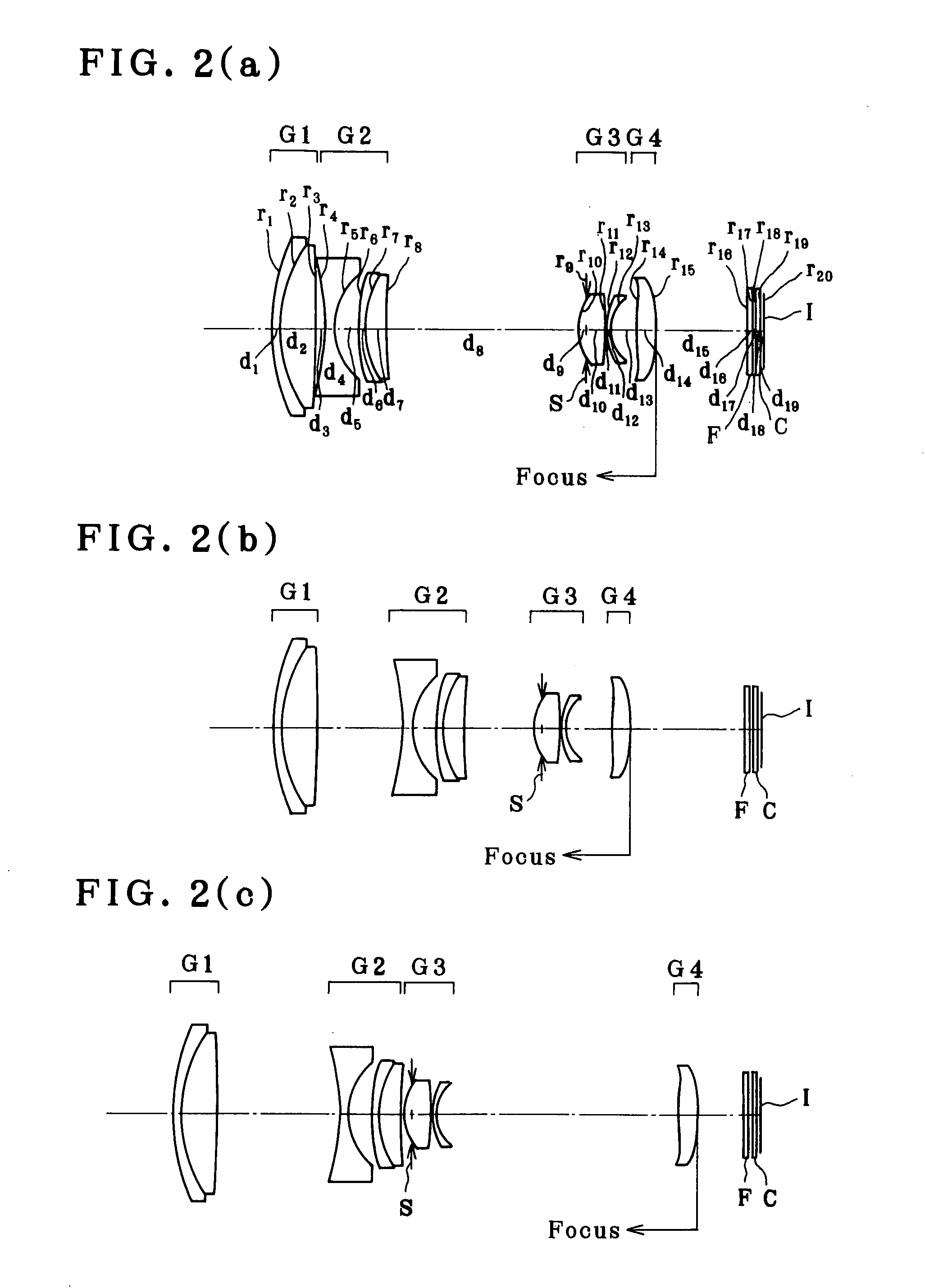
example 2
[0125]
r1 = 23.809d1 = 1.00nd1 = 2.00170νd1 = 20.64r2 = 16.163d2 = 4.10nd2 = 1.76802νd2 = 49.24r3 = −117.361d3 = (Variable)(Aspheric)r4 = −15.370d4 = 1.00nd3 = 1.80610νd3 = 40.92(Aspheric)r5 = 8.729 (Aspheric)d5 = 2.60r6 = 24.332 (Aspheric)d6 = 0.80nd4 = 1.80610νd4 = 40.92r7 = 9.689d7 = 2.40nd5 = 2.00170νd5 = 20.64r8 = 35.185d8 = (Variable)r9 = ∞ (Stop)d9 = −1.00r10 = 5.112 (Aspheric)d10 = 3.10nd6 = 1.49700νd6 = 81.54r11 = −111.184d11 = 0.10(Aspheric)r12 = 6.163d12 = 0.45nd7 = 1.84666νd7 = 23.78r13 = 4.167d13 = (Variable)r14 = 29.093d14 = 2.20nd8 = 1.49700νd8 = 81.54(Aspheric)r15 = −23.912d15 = (Variable)(Aspheric)r16 = ∞d16 = 0.50nd9 = 1.54771νd9 = 62.84r17 = ∞d17 = 0.50r18 = ∞d18 = 0.50nd10 = 1.51633νd10 = 64.14r19 = ∞d19 = 0.40r20 = ∞(Imaging plane)Aspherical Coefficients3rd surfaceK = 0.000A4 = 7.53316 × 10⁻⁶A6 = −1.21007 × 10⁻⁸A8 = 3.56951 × 10⁻¹¹A10 = 04th surfaceK = 0.000A4 = 4.32539 × 10⁻⁴A6 = −3.97769 × 10⁻⁶A8 = 2.06282 × 10⁻⁸A10 = 05th surfaceK = 0.000A4 = 5.18041 × 10⁻⁵A6 ...
example 3
[0126]
r1 = 28.071d1 = 1.00nd1 = 2.00069νd1 = 25.46r2 = 18.303d2 = 5.90nd2 = 1.74320νd2 = 49.34r3 = 787.550d3 = (Variable)r4 = −354.880d4 = 1.00nd3 = 1.88300νd3 = 40.76r5 = 9.906d5 = 3.80r6 = −19.516d6 = 0.80nd4 = 1.88300νd4 = 40.76r7 = 136.347d7 = 0.10r8 = 29.976d8 = 2.50nd5 = 1.92286νd5 = 20.88r9 = −40.507d9 = (Variable)r10 = ∞ (Stop)d10 = 0.50r11 = 12.136d11 = 2.30nd6 = 1.49700νd6 = 81.54(Aspheric)r12 = −25.267d12 = 0.10(Aspheric)r13 = 8.094d13 = 3.77nd7 = 1.74320νd7 = 49.34r14 = 9.619d14 = 0.70nd8 = 2.00170νd8 = 20.64r15 = 5.417d15 = (Variable)r16 = 11.630d16 = 2.00nd9 = 1.53113νd9 = 55.80(Aspheric)r17 = 89.127d17 = (Variable)(Aspheric)r18 = ∞d18 = 0.50nd10 = 1.54771νd10 = 62.84r19 = ∞d19 = 0.50r20 = ∞d20 = 0.50nd11 = 1.51633νd11 = 64.14r21 = ∞d21 = 0.40r22 = ∞(Imaging plane)Aspherical Coefficients11th surfaceK = 0.890A4 = −2.43409 × 10⁻⁴A6 = −9.55187 × 10⁻⁶A8 = 2.84768 × 10⁻⁷A10 = −1.66816 × 10−812th surfaceK = 4.073A4 = −4.71267 × 10⁻⁵A6 = −7.23416 × 10⁻⁶A8 = 1.62747 × 10⁻⁷A10 ...
PUM
 Abstract
Description
Claims
Application Information