Ultrasonic transducer, manufacturing method of ultrasonic transducer, and ultrasonic endoscope

a manufacturing method and ultrasonic technology, applied in the direction of mechanical vibration separation, catheters, applications, etc., can solve the problems of non-uniform cavity shape and distortion of sealing portion shap

Active Publication Date: 2008-04-17
OLYMPUS CORP
View PDF6 Cites 22 Cited by
  • Summary
  • Abstract
  • Description
  • Claims
  • Application Information

AI Technical Summary

Benefits of technology

[0008] An ultrasonic transducer according to the present invention comprises: two or more ultrasonic transducer cells, each of which includes a lower electrode, a first insulating layer placed on the lower electrode, a cavity placed on the first insulating layer, a second insulating layer placed on the cavity, and an upper electrode placed above the second insulating layer; channels which communicate the cavities with each other; the second insulating layer placed on the channels; holes formed in the second insulating layer placed on the channels; and sealing portions which seal the holes, where that part of the sealing portions which enters the channels is the same in cross-sectional shape as the holes.

Problems solved by technology

With conventional techniques, however, material used to form the sealing portions is deposited in the cavities more than necessary, distorting shape of the sealing portions.
This makes shape of the cavities non-uniform.

Method used


Image

  • Ultrasonic transducer, manufacturing method of ultrasonic transducer, and ultrasonic endoscope
  • Ultrasonic transducer, manufacturing method of ultrasonic transducer, and ultrasonic endoscope
  • Ultrasonic transducer, manufacturing method of ultrasonic transducer, and ultrasonic endoscope

Examples


first embodiment

[0052] The ultrasonic transducer according to the present invention will be described below with reference to FIGS. 4 to 19.

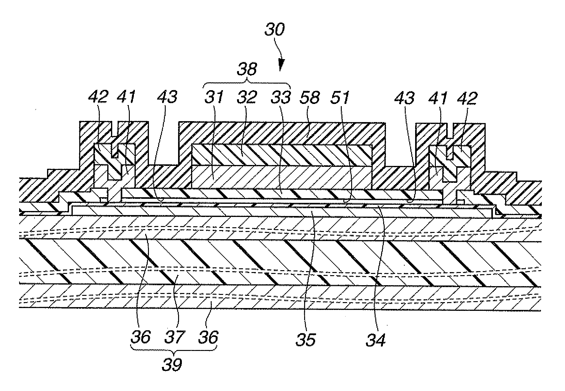
[0053]FIG. 4 is a top view of an ultrasonic transducer, FIG. 5 is an enlarged view of encircled part V in FIG. 4, FIG. 6 is a cross-sectional view of ultrasonic transducer cells taken along VI-VI line in FIG. 5, FIG. 7 is a cross-sectional view of the ultrasonic transducer cells taken along VII-VII line in FIG. 5, FIG. 8 is a cross-sectional view of a wafer with a thick oxide film, FIG. 9 is a cross-sectional view showing a fabrication process of ultrasonic transducer cells after lower electrodes are formed on the wafer with the thick oxide film, FIG. 10 is a cross-sectional view showing the fabrication process of ultrasonic transducer cells after a first insulating layer is formed, FIG. 11 is a cross-sectional view showing the fabrication process of ultrasonic transducer cells after a sacrificial layer is formed, FIG. 12 is a cross-sectional view showing the ...

second embodiment

[0094] Next, a second embodiment will be described with reference to FIGS. 20 and 23.

[0095]FIGS. 20 and 23 concern the second embodiment, where FIG. 20 is a cross-sectional view showing a fabrication process of ultrasonic transducer cells after upper electrodes and sealing portions are formed by etching, FIG. 21 is a cross-sectional view showing the fabrication process of ultrasonic transducer cells after a protective film is formed, FIG. 22 is a cross-sectional view showing the fabrication process of ultrasonic transducer cells after a parylene film is formed, FIG. 23 is a flowchart showing a fabrication process of ultrasonic transducer cells.

[0096] In the following description, the same components as those in the first embodiment will be denoted by the same reference numerals as the corresponding components in the first embodiment, and description thereof will be omitted and only differences from the first embodiment will be described.

[0097] The fabrication method of the transd...


PUM

PropertyMeasurementUnit
anglesaaaaaaaaaa
thicknessaaaaaaaaaa
thicknessaaaaaaaaaa

Abstract

An ultrasonic transducer according to the present invention includes: two or more ultrasonic transducer cells, each of which has a lower electrode, a first insulating layer placed on the lower electrode, a cavity placed on the first insulating layer, a second insulating layer placed on the cavity, and an upper electrode placed above the second insulating layer; channels which communicate the cavities with each other; the second insulating layer placed on the channels; holes formed in the second insulating layer placed on the channels; and sealing portions which seal the holes, where that part of the sealing portions which enters the channels is the same in cross-sectional shape as the holes.

Description

[0001] This application claims benefit of Japanese Applications No. 2006-278043 filed on Oct. 11, 2006 and No. 2007-263696 filed on Oct. 9, 2007 the contents of which are incorporated by this reference. BACKGROUND OF THE INVENTION [0002] 1. Field of the Invention [0003] The present invention relates to a capacitive type ultrasonic transducer, a fabrication method for the ultrasonic transducer, and an ultrasonic endoscope which has the ultrasonic transducer in an ultrasonic transmission and reception portion. [0004] 2. Description of the Related Art [0005] To form cavities in an ultrasonic transducer, a method is known which creates cavities and channels communicating the cavities with each other by using a sacrificial layer, forms an insulating layer on the sacrificial layer, creates holes in the insulating layer, pours a chemical agent or gas to dissolve the sacrificial layer, and thereby removes the sacrificial layer. This method can form cavities under the insulating layer. Besid...

Claims


Application Information

Patent Timeline
Patent Type & Authority Applications(United States)
IPC IPC(8): H04R31/00A61B8/00B06B1/06H04R17/00
CPCA61B8/12A61B8/4488B06B1/0292Y10T29/42Y10T29/49005Y10T29/49155A61B8/445
Inventor MATSUMOTO, KAZUYAOHTA, RYOHASEGAWA, MAMORUADACHI, HIDEOWAKABAYASHI, KATSUHIRO
Owner OLYMPUS CORP
Why Eureka
Try Eureka