Display apparatus and display method

a display device and display device technology, applied in electrical devices, network topologies, radio transmission, etc., can solve the problems of inability to perform link connection and communication between dsrc roadside devices or between dsrc in-vehicle communication apparatuses, inability to perform inter-vehicle communication according to the conventional dsrc communication standard, and inability to perform inter-vehicle communication using dsrc communication between arbitrary vehicles

Inactive Publication Date: 2008-04-17
PANASONIC CORP
View PDF15 Cites 80 Cited by
  • Summary
  • Abstract
  • Description
  • Claims
  • Application Information

AI Technical Summary

Benefits of technology

[0014]One aspect of an inter-vehicle communication method of the present invention achieves the above object by having: a frame control signal transmitting step of one of a plurality of in-vehicle communication apparatuses having functions of both a base station and a mobile station transmitting a frame control signal; a step of the in-vehicle communication apparatus that receives the frame control signal during a frame control signal reception standby operation analyzing the received frame control signal; a step of, when the in-vehicle communication apparatus that transmitted the frame control signal can be recognized by means of the analysis, transmitting a channel affiliation request signal containing the station's own address; a step of the in-vehicle communication apparatus that transmitted the frame control signal receiving the channel affiliation request signal during a channel affiliation request reception standby operation and functioning as a base station correspondent in-vehicle communication apparatus; and an inter-vehicle communication step of the base station correspondent in-vehicle communication apparatus and a mobile station correspondent in-vehicle communication apparatus that is the in-vehicle communication apparatus

Problems solved by technology

Therefore, link connection and communication cannot be performed between DSRC roadside devices or between DSRC in-vehicle communication apparatuses.
There is thus a problem in that inter-vehicle communication cannot be performed according to the conventional DSRC communicat

Method used


Image

  • Display apparatus and display method
  • Display apparatus and display method
  • Display apparatus and display method

Examples


embodiment 1

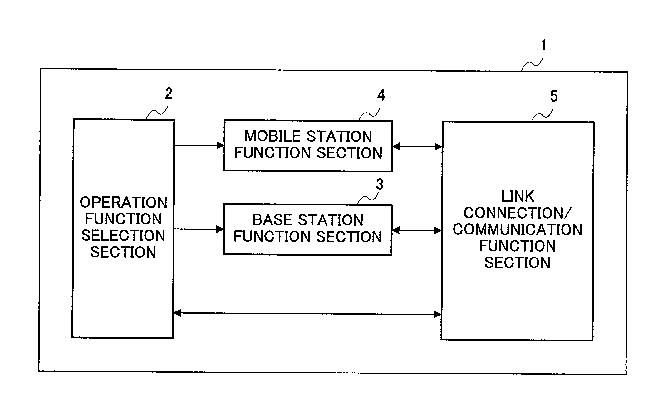
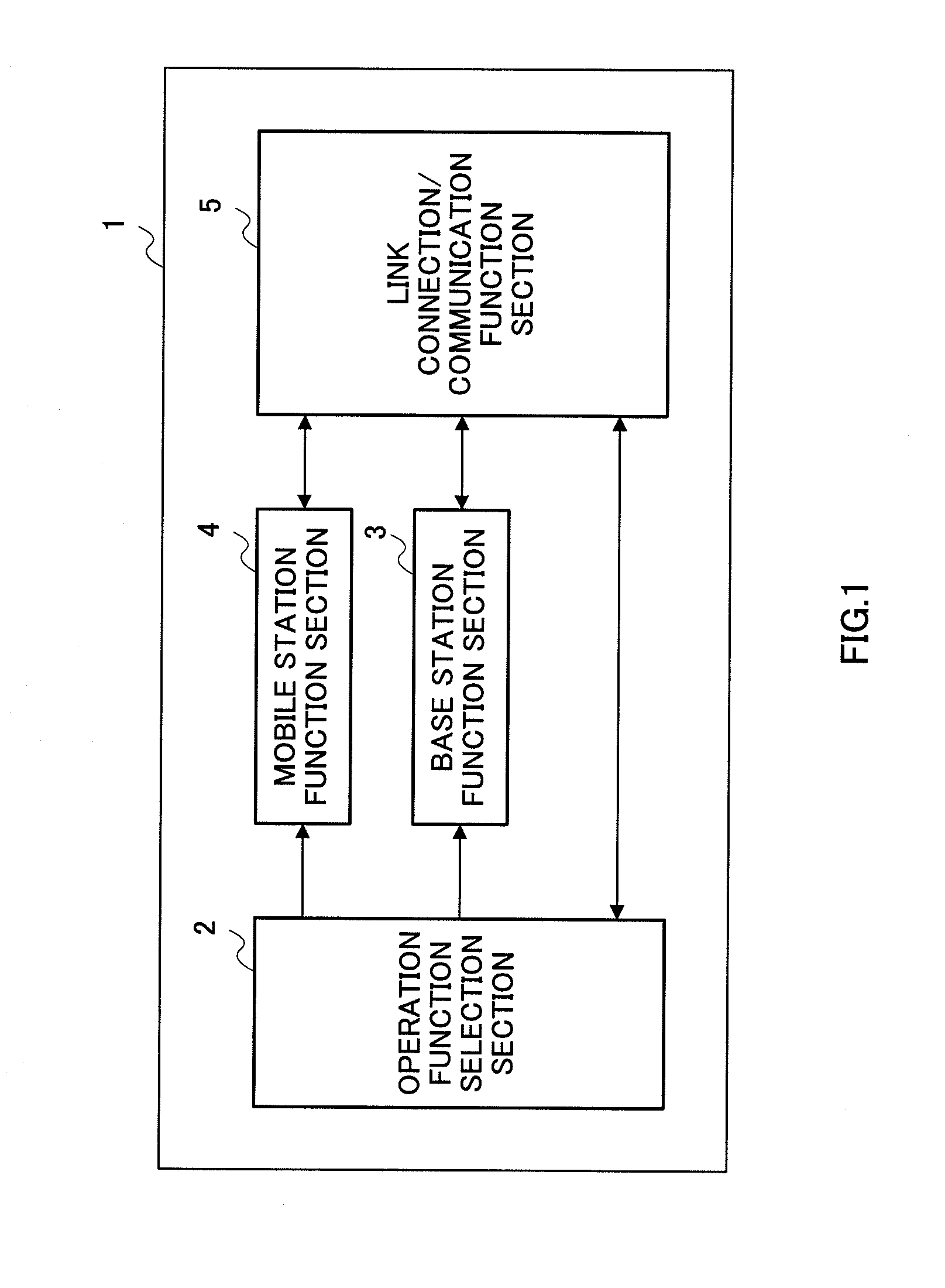
[0022]FIG. 1 is a block diagram showing the configuration of a DSRC in-vehicle communication apparatus according to Embodiment 1 of the present invention. DSRC in-vehicle communication apparatus 1 is mainly composed of an operation function selection section 2, a base station function section 3, a mobile station function section 4, and a link connection / communication function section 5.

[0023]Operation function selection section 2 selects base station function section 3 or mobile station function section 4 by means of a setting operation by the user of DSRC in-vehicle communication apparatus 1, or by means of a user setting operation plus DSRC communication with another DSRC apparatus, thereby selecting whether DSRC in-vehicle communication apparatus 1 operates as a base station or a mobile station. Specifically, operation function selection section 2 performs sequential and repeated control of a frame control signal transmit operation, frame control signal standby operation, and cha...

embodiment 2

[0059]FIG. 3 is a drawing explaining the operation of an inter-vehicle communication system according to Embodiment 2 of the present invention. The operation of an inter-vehicle communication system according to Embodiment 2 is described below with reference to FIG. 3. A DSRC in-vehicle communication apparatus used in an inter-vehicle communication system according to Embodiment 2 has the same configuration as DSRC in-vehicle communication apparatus 1 shown in FIG. 1, and Embodiment 2 is described below using the reference codes in FIG. 1.

[0060]When a DSRC in-vehicle communication apparatus 1 is set to operate by determining whether to operate as a base station or as a mobile station by means of a base station / mobile station determination operation setting directive 200 from operation function selection section 2 of DSRC in-vehicle communication apparatus 1, DSRC in-vehicle communication apparatus 1 performs FCMC transmission 201, ACTC reception standby 202, and FCMC reception stand...

embodiment 3

[0065]FIG. 4 is a drawing explaining the operation of an inter-vehicle communication system according to Embodiment 3 of the present invention. FIG. 4 illustrates a case in which a pair of DSRC in-vehicle communication apparatuses shown in FIG. 1 are present. In FIG. 4, this pair of DSRC in-vehicle communication apparatuses are designated DSRC in-vehicle communication apparatus A and DSRC in-vehicle communication apparatus B. In Embodiment 3, it is not initially established whether this pair of DSRC in-vehicle communication apparatuses A and B operate as a base station or mobile station, and both are set as operating as determined by means of communication. However, to make the drawing easier to understand, it will here be assumed that DSRC in-vehicle communication apparatus A finally sets its operation after determining itself to be a base station, and DSRC in-vehicle communication apparatus B finally sets its operation after determining itself to be a mobile station.

[0066]The oper...


PUM


Abstract

A DSRC in-vehicle communication apparatus (1) operates as a base station based on the DSRC communication standard when a base station function section (3) is selected by an operation function selection section (2), and operates as a mobile station based on the DSRC communication standard when a mobile station function section (4) is selected. After a plurality of vehicles equipped with a DSRC in-vehicle communication apparatus (1) have been disposed, an inter-vehicle communication system is constructed by the function of each DSRC in-vehicle communication apparatus (1) being selected, and vehicles whose function has been selected as base station or mobile station performing DSRC communication.

Description

CROSS REFERENCE TO RELATED APPLICATIONS[0001]The disclosures of Japanese Patent Application No. 2006-277929 filed on Oct. 11, 2006, including the specifications, drawings and abstracts are incorporated herein by reference in their entirety.BACKGROUND OF THE INVENTION[0002]1. Field of the Invention[0003]The present invention relates to an inter-vehicle communication method and in-vehicle communication apparatus that perform DSRC (Dedicated Short Range Communication) communication.[0004]2. Description of the Related Art[0005]The current DSRC communication standard (ARIB STD-T75) is used for implementing various ITS services such as fee payment and data / information two-way communication. With regard to DSRC (Dedicated Short Range Communication), “short-range communication system standard ARIB STD-T75” has been drawn up by the incorporated company “Association of Radio Industries and Businesses.” In this description, communication in accordance with this “short-range communication syste...

Claims


Application Information

Patent Timeline
IPC IPC(8): H04B7/00
CPCH04W48/12H04W84/18H04W48/20
Inventor OYAMA, SHIGEKI
Owner PANASONIC CORP
Why Eureka
Try Eureka