Method for charging rechargeable battery

Inactive Publication Date: 2008-04-24
SANYO ELECTRIC CO LTD
View PDF2 Cites 22 Cited by
  • Summary
  • Abstract
  • Description
  • Claims
  • Application Information

AI Technical Summary

Benefits of technology

[0009] However, this type of known power supply has the following disadvantages. In a case where a battery with voltage higher than a predetermined voltage of the charge power supply is mounted and a charge process starts, constant voltage Feedback operates so that the charge power supply output decreases. In this case, the output may stop or intermittently oscillate.
[0015] 5. But the output voltage does not vary and remains 4.21 V of the battery voltage, thus, the Feedback portion continuously provides the signal that reduces the output.
[0026] Therefore, the present invention is made to solve the above disadvantages, and its object is to provide a method for charging a rechargeable battery by using a charge power supply that charges the rechargeable battery at constant voltage, the method preventing intermittent oscillation and power supply output stop.
[0029] In addition, this method can take measures against a power supply stop and intermittent oscillation by means of conventional circuitry construction without providing additional components.

Problems solved by technology

However, this type of known power supply has the following disadvantages.

Method used


Image

  • Method for charging rechargeable battery
  • Method for charging rechargeable battery
  • Method for charging rechargeable battery

Examples


Embodiment Construction

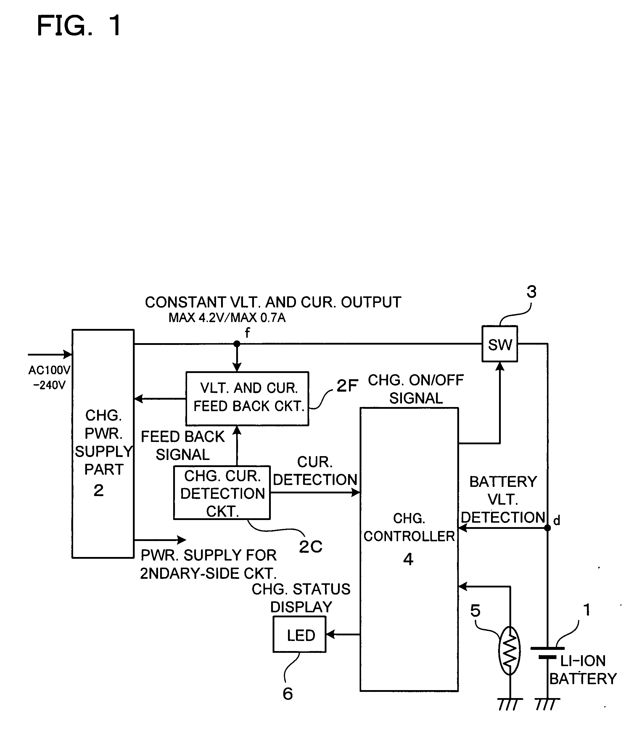
[0033] A charger A with a charge circuit shown in FIG. 1 includes a charge power supply portion 2 (charge power supply), a switching element 3, a charge control portion 4, and a temperature sensor 5 such as thermistor. The charge power supply portion 2 is a constant-voltage and constant-current power supply (Max. 4.2 V, and Max. 0.7 A) that provides charge current to a battery 1 which is detachably mounted to the charger. The switching element 3 is connected between the charge power supply 2 and the battery 1, and controls and adjusts the charge current for the battery 1. The charge control portion 4 includes a microcomputer that turns the switching element 3 ON / OFF, and thus controls and adjusts the charge current. The temperature sensor 5 detects the battery temperature, and provides a temperature signal to the charge control portion 4. A rechargeable battery such as lithium-ion (Li-ion) rechargeable battery and lithium-polymer (Li-polymer) rechargeable battery can be used as the ...


PUM


Abstract

A method for charging a rechargeable battery by using a charge power supply that charges the rechargeable battery at constant voltage is provided. A pulse charge operation is performed at a charge process start. The charge process is stopped when current in the pulse charge operation is not greater than a predetermined value and it is determined that the rechargeable battery is in a full-charge state. On the other hand, the rechargeable battery is charged at constant voltage when the current in the pulse charge operation is greater than the predetermined value.

Description

BACKGROUND OF THE INVENTION [0001] 1. Field of the Invention [0002] The present invention relates a method for charging a rechargeable battery. [0003] 2. Description of the Related Art [0004] The following Patent Document discloses a charger which charges a lithium-ion rechargeable battery. As shown in FIGS. 4 and 5 of this Document, this type of charger includes a power supply portion 1, a charge control switch 2 which is provided on a charge path, and a calculation circuit 3 (microcomputer) which detects battery voltage and charge current, and controls the power supply portion 1 and the charge control switch 2. This power supply portion 1 includes feedback circuits for current and voltage. The power supply portion 1 includes a rectifying circuit 8, a switching portion 9, a conversion transformer 11, a PWM control circuit 13, and a photocoupler 17. The rectifying circuit 8 converts alternating current into direct current. The switching portion 9 converts the direct current of the r...

Claims


Application Information

Patent Timeline
IPC IPC(8): H01M10/44
CPCH01M10/052H01M10/0525H02J7/0077H01M10/443H02J7/0073H01M10/44H02J7/0071H02J7/00712Y02E60/10
Inventor YAMASHITA, TAKAHIROFUKUDA, TOMOYA
Owner SANYO ELECTRIC CO LTD
Why Eureka
Try Eureka