
Antenna with Shaped Asymmetric Main Reflector and Subreflector with Asymmetric Waveguide Feed

a technology of asymmetric reflector and asymmetric waveguide feed, which is applied in the direction of antennas, electrical equipment, etc., can solve the problems of low profile form factor, inconvenient installation, and inability to meet the needs of many applications,

Inactive Publication Date: 2008-04-24
HARRIS CORP
View PDF24 Cites 169 Cited by
  • Summary
  • Abstract
  • Description
  • Claims
  • Application Information

AI Technical Summary

Benefits of technology

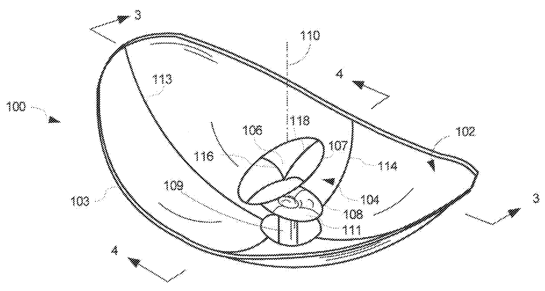
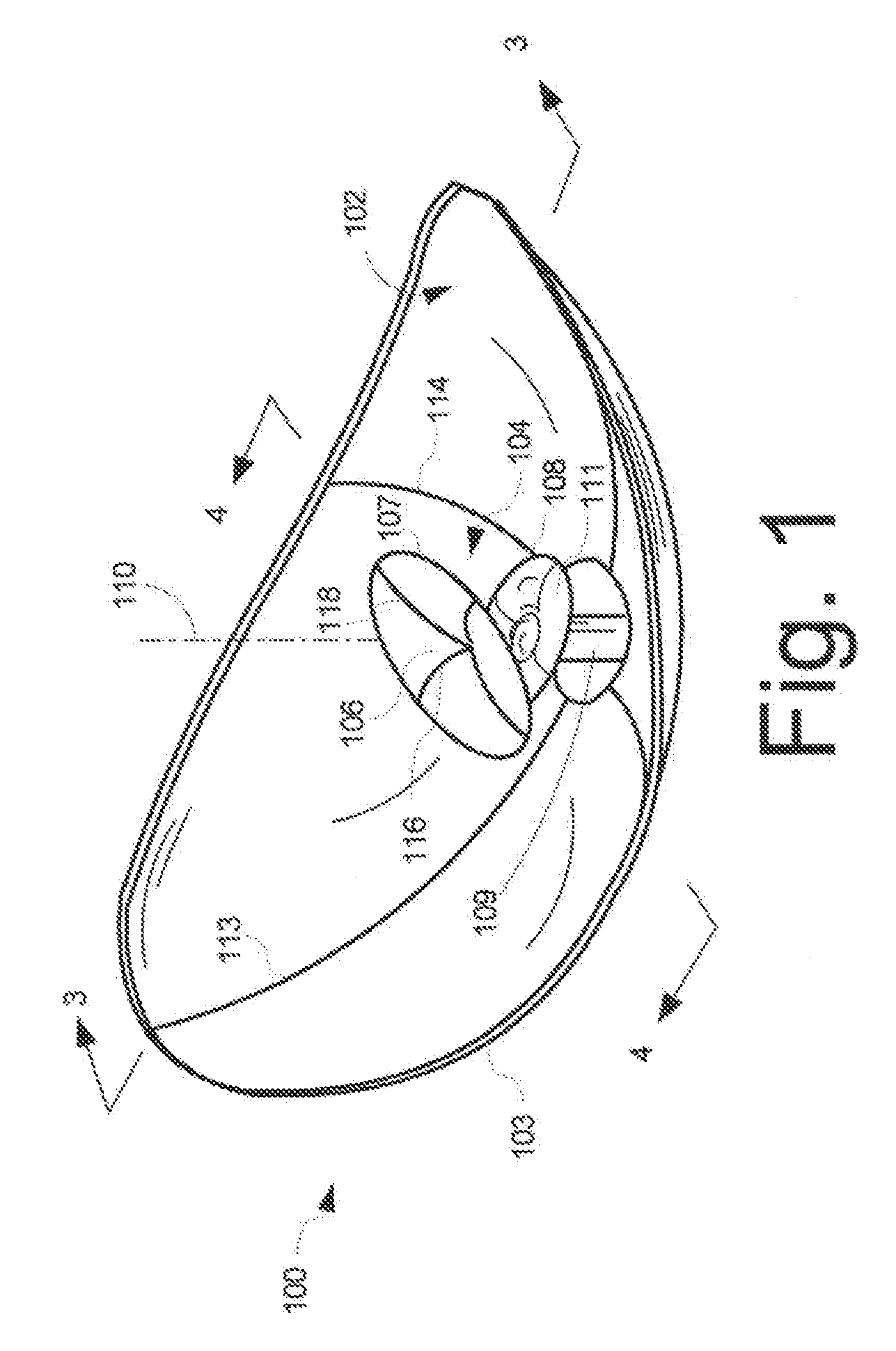
[0011]The horn antenna associated with the feed system is installed at a first location separated by a gap from a vertex of the subreflector on the boresight axis of the antenna. In a coupled configuration, the gap is less than four wavelengths at an operational frequency at which the low-profile antenna system is designed to operate. The feed system defines a focal ring for illuminating the main reflector at an operational frequency at which the low-profile antenna system is designed to operate. Depending on the shape of the main reflector and subreflector, the focal ring can be symmetric or asymmetric.
[0012]Considered in a mere general sense, the invention is directed to a low-profile reflector antenna system which includes a main reflector fo...

Problems solved by technology

For example, a parabolic reflector antenna with a large circularly symmetric edge configuration might provide a desired electrical performance but would be unacceptable for many applications (airborne, ship, ground) which demand low profile form factors.
However, phased arrays tend to be very complex and expensive systems.
While such techniques are effective for the purpose of providing a lower profile, they are also known to introduce some problems.
For example, modifying a ring-focus reflector in this way is an inefficient approach if gain is to be optimized.
It also produces unwanted sidelobes, which usually result from edge diffraction.

Method used


Image

  • Antenna with Shaped Asymmetric Main Reflector and Subreflector with Asymmetric Waveguide Feed
  • Antenna with Shaped Asymmetric Main Reflector and Subreflector with Asymmetric Waveguide Feed
  • Antenna with Shaped Asymmetric Main Reflector and Subreflector with Asymmetric Waveguide Feed

Examples


Embodiment Construction

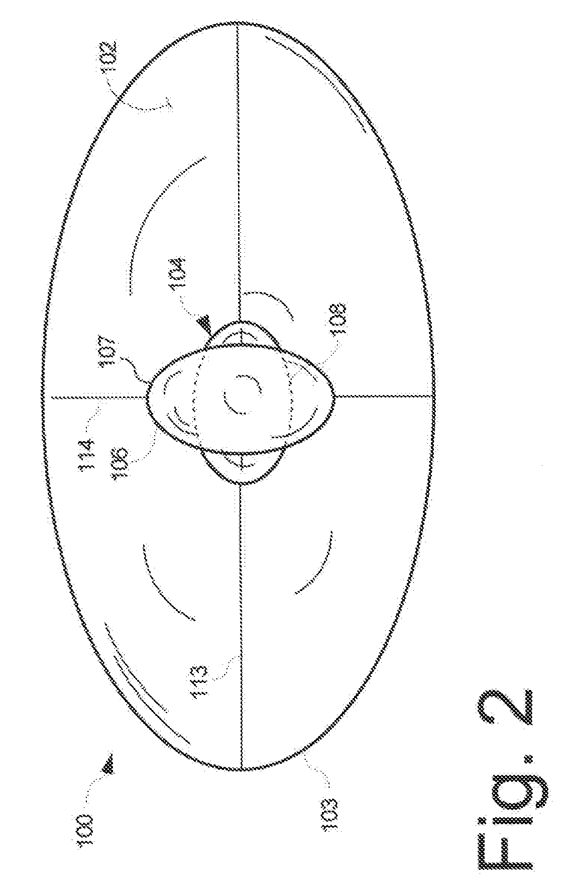
[0020]Shaped ring focus antennas typically have a main reflector and a subreflector, each formed from a conductive material or mesh. The main reflector is usually formed as a shaped surface of revolution defined by a split, approximately parabolic, curve. The subreflector is typically formed as a shaped surface of revolution defined by an approximately, but not precisely, elliptical curve. The main reflector and the subreflector each have a symmetric circular edge configuration in conventional designs. In particular, when the reflectors are viewed along a boresight axis of the antenna, the perimeter or edge of each unit forms a symmetric circular profile. Although these types of shaped ring focus antennas with circular edge configurations work well with regard to electrical performance, their form factor does not work well in all applications. For example, a conventional ring focus antenna design will have a relatively high profile when mounted on a vehicle if the antenna is to be c...


PUM


Abstract

A low-profile antenna system includes a main reflector (102) formed as a shaped main reflector surface that is approximately, but not precisely, parabolic. The main reflector (102) has a main reflector edge configuration (103) that is asymmetric. A feed system (104) for the main reflector includes a subreflector (106) formed as a shaped subreflector surface that is approximately, but not precisely, elliptical. The subreflector has a subreflector edge configuration (107) that is also asymmetric. An RF feed horn (108) associated with the feed system 104 has an aperture profile which also has an asymmetric shape.

Description

BACKGROUND OF THE INVENTION[0001]1. Statement of the Technical Field[0002]The invention concerns ring-focus reflector antenna systems, and more particularly asymmetrical reflector antennas that provide a low profile and improved performance.[0003]2. Description of the Related Art[0004]Satellite communication antennas are used in a wide variety of applications for providing terrestrial communications with earth orbiting satellites. The most common type of antennas used for satellite communications are dish reflector antennas. Dish reflector antennas generally are comprised of two main components, namely a reflector and a subreflector. The most common main reflectors among the high-gain reflector antennas make use of a parabolic surface, which is formed by rotating the arc of a parabola about the line joining the vertex and the focal point. When viewed along boresight (i.e., from the front), antenna reflectors typically have various shapes. For example, a paraboloid can have an edge c...

Claims


Application Information

Patent Timeline
IPC IPC(8): H01Q13/00
CPCH01Q19/19
Inventor KRALOVEC, JAYGOTHARD, GRIFFINMEEHAN, ROBERTHOWLEY, ROBERTZIMMERMAN, KURT
Owner HARRIS CORP
Learn More