
Microplate with fewer peripheral artifacts

a microplate and peripheral technology, applied in the field of microwell sample plates, can solve the problems of inducing artifacts, affecting the quality of microplates,

Inactive Publication Date: 2008-04-24
XU LIN
View PDF4 Cites 108 Cited by
  • Summary
  • Abstract
  • Description
  • Claims
  • Application Information

AI Technical Summary

Benefits of technology

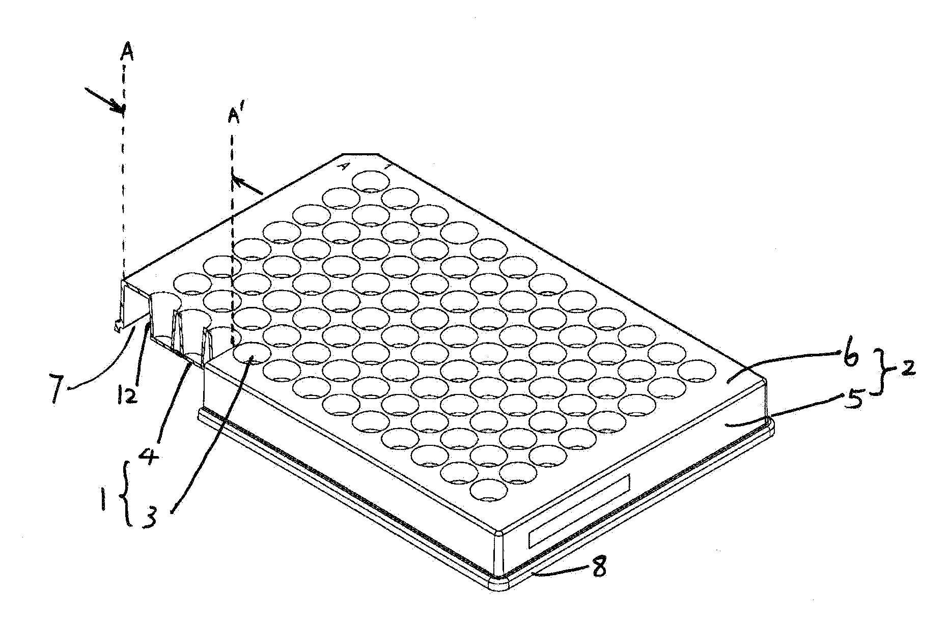
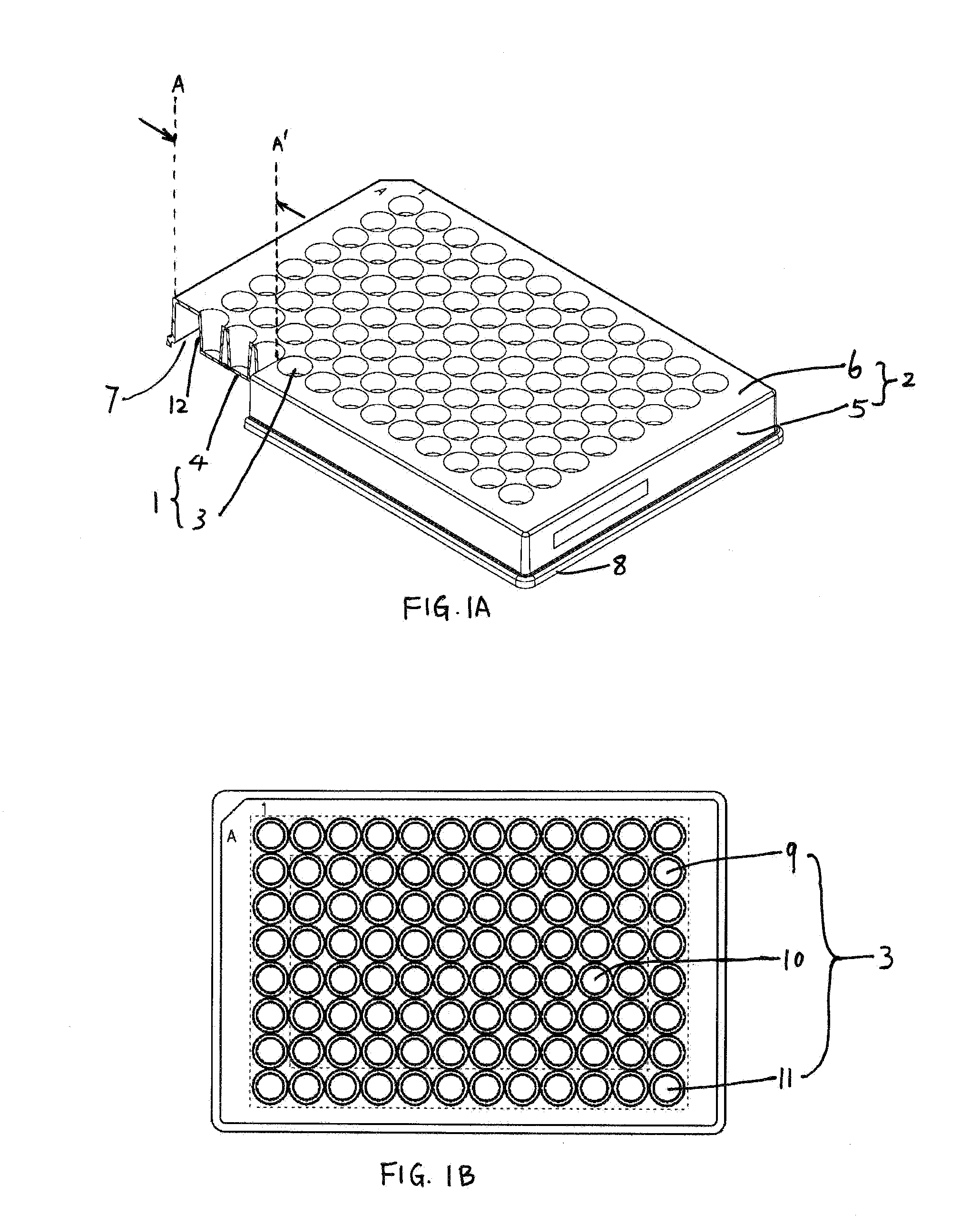
[0022]The present invention has been made to solve the problems noted above and provide a microplate that has fewer artifacts at peripheral wells, especially at corner wells.
[0023]A primary object of the invention is to provide a microplate eliminating the non-experimental slots that may avail physical differences, such as the thermal preference, at peripheral wells, especially at corner wells.
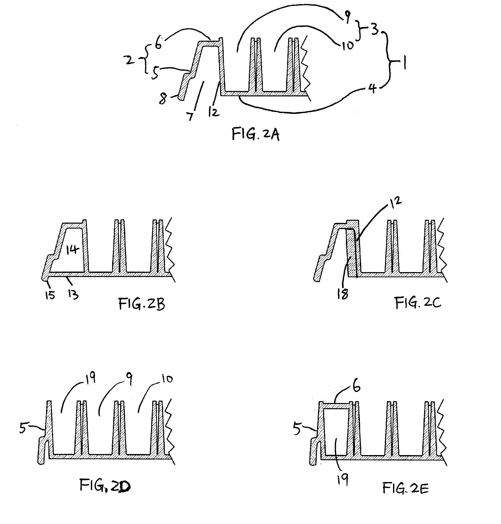
[0024]A second object of the invention is to provide a microplate able to retard some of the surrounding influences, i.e. thermal transmission, from the ambience via side-walls sideward to the experimental unit, and / or accelerate thermal transmission from the ambience upward and / or downward to the experimental unit.
[0025]A third object of the invention is to provide a microplate which achieves the alleviation or elimination of disparity of light interferences at peripheral wells compared to internal wells.
[0029]In another preferred embodiment, a microplate according to the present invention further possesses enhancement(s) at the side-wall; the enhanced side-walls may retard some of the surrounding disparities, like the thermal preference, at peripheral wells.

Problems solved by technology

However, there are some considerable limitations related to current commercially available microplates due to the influences of surrounding factors.
Peripheral artifacts also appear when using micro-wells to store liquid samples.
This will bring a different air pattern at peripheral wells, which induces artifacts.
Due to the current design of conventional microplates, pressures and tensions are not as evenly distributed to edges and corners of the bottom as to the internal areas of the bottom.
This kind of uneven bottom might go along with problems in molecule binding ability, biased penetration and / or reflection of light, all of which might affect later-on spectrophotometric measurements.
And the most likely problematic wells should be at edges and / or corners.
Nevertheless, even if manufacturing a totally even bottom is no longer a problem, there are still some visible differences between peripheral wells and internal wells.
It is inevitable that the above-mentioned limitations have caused some inaccurate experimental results, for example, increase or decrease in spectrophotometric reading values, in the conventional microplates.

Method used


Image

  • Microplate with fewer peripheral artifacts
  • Microplate with fewer peripheral artifacts
  • Microplate with fewer peripheral artifacts

Examples


embodiment 4

Preferred Embodiment 4

[0087]Alternatively to the preferred embodiment 1 possessing a bottom elongation 13, a preferred embodiment 4 according to the present invention has a releasable undercover in addition to a conventional microplate, and the said undercover is used to cover the bottom of the microplate from underneath when needed, especially when a temperature change is expected. The purpose of this undercover is to make a tight closure over the lower ambience, including the non-experimental slots, and prevent the ambient air from refreshing into the non-experimental slots. The said undercover is preferably co-packaged with the microplate as an assembly; More preferably, the said undercover is a separately-cataloged universal undercover.

[0088]In an alternative preferred embodiment, the microplate according to the present invention is similar to, or even the same as, one of any conventional microplates, but co-packaged with a separate and / or affixed sheet informing microplate user...


PUM


Abstract

The current invention relates to an improved microplate. The microplate is characterized by modified quadrilateral edges, which bring less artificially induced inaccuracies in peripheral wells, especially in corner wells. Preferably, the microplate possesses a bottom that is elongated to cover the non-experimental slots. The microplate might further comprise sham wells.

Description

CROSS-REFERENCE TO RELATED APPLICATIONS[0001]This application is claiming the benefit of U.S. provisional patent application Ser. No. 60 / 862,419, filed Oct. 20, 2006 by the present inventor.FEDERALLY SPONSORED RESEARCH[0002]Not ApplicableSEQUENCE LISTING OR PROGRAM [0003]Not ApplicableBACKGROUND[0004]1. Field of the Invention[0005]The present invention relates to a micro-well sample plate which is commonly referred to as a microplate and which is used to hold a large number of samples in a standardized format. More specifically, the present invention relates to a microplate with modified quadrilateral edges, which bring less artificially induced inaccuracies in peripheral wells, especially in corner wells.[0006]2. Prior Art[0007]Microplates are widely used for storing, filtering, incubating and detecting samples in chemical experiments, biological assays, medical tests and the like. For example, a microplate might be used as micro-containers to store, filter, prepare, or incubate mu...

Claims


Application Information

Patent Timeline
Patent Type & Authority Applications(United States)
IPC IPC(8): B01L3/00
CPCB01L3/50851B01L2300/18B01L2300/0829B01L2200/14
Inventor XU, LIN
Owner XU LIN
Learn More