Method for Friction-Stir-Welding Hollow Workpieces

a technology of friction-stir welding and workpieces, which is applied in the direction of manufacturing tools, machines/engines, transportation and packaging, etc., can solve the problems of difficulty in disposing the support member at a proper position, risk of occurrence of defect in the joint portion, and reduce the wall thickness of the joint portion, so as to prevent an impairment of the joining strength

Inactive Publication Date: 2008-04-24
SHOWA DENKO KK
View PDF2 Cites 14 Cited by
  • Summary
  • Abstract
  • Description
  • Claims
  • Application Information

AI Technical Summary

Benefits of technology

[0029]The method of par. 7) can reduce a reduction in wall thickness of a joint portion, thereby preventing an impairment in joining strength.
[0030]With the method of par. 8), when the two workpieces to be joined and the support member are assembled, there can be prevented formation of a gap between the inner perimeter surfaces of the butt end portions of the workpieces and the corresponding outer perimeter surfaces of the opposite support portions of the support member, thereby providing a sound joint portion free from occurrenc...

Problems solved by technology

However, when arc welding is used to join heat-treatment-type alloys, such as JIS A6000 family alloys, heat input during welding has caused an impairment in strength, and occurrence of thermal strain in a heat affected zone.
However, when the support member is press-fitted into the butt end portions of the two workpieces to be joined, difficulty ...

Method used


Image

  • Method for Friction-Stir-Welding Hollow Workpieces
  • Method for Friction-Stir-Welding Hollow Workpieces
  • Method for Friction-Stir-Welding Hollow Workpieces

Examples


embodiment 1

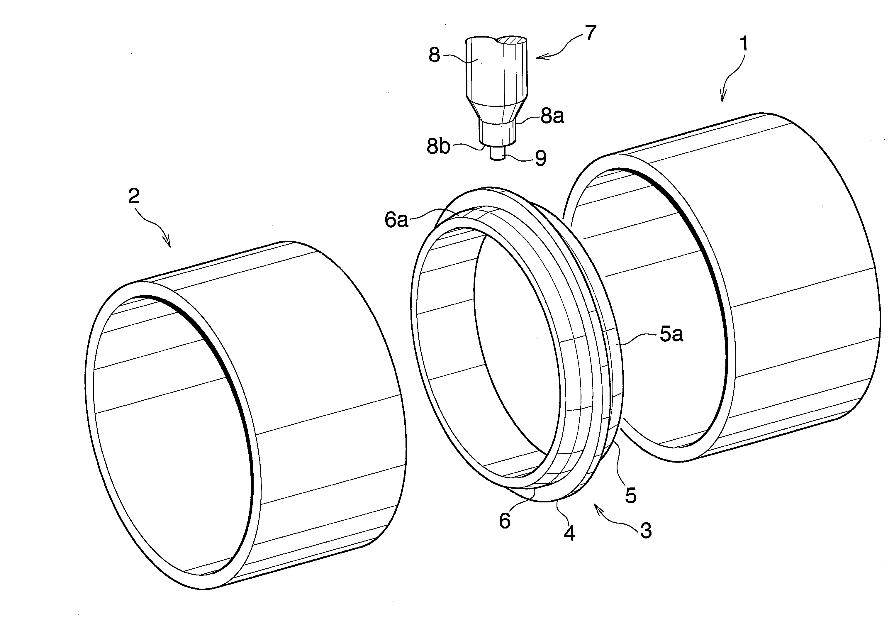
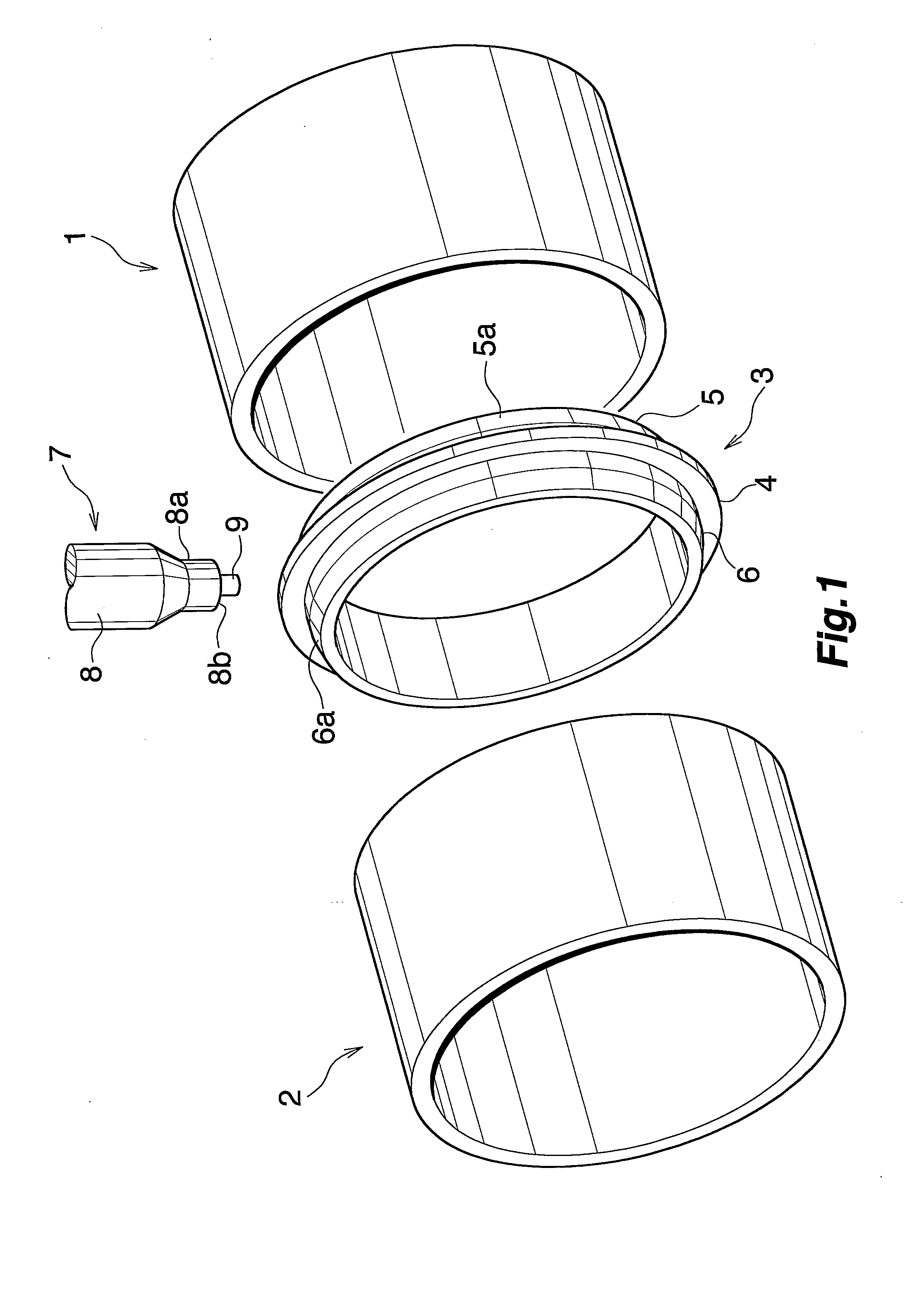
[0036]The present embodiment is shown in FIGS. 1 to 3.

[0037]First, two cylindrical workpieces (1) and (2), each opened at opposite ends, are prepared as members to be joined. Also, an annular (short, cylindrical) support member (3) is prepared. The workpieces (1) and (2) are of the same wall thickness and the same inside diameter; i.e., the inner circumferential length is constant along the overall axial length, so that butt end portions of the workpieces (1) and (2) are of the same wall thickness and the same inner circumferential length. An annular, radially outward projection (4) is integrally formed on the outer circumferential surface of the support member (3) in an intermediate region in the axial direction of the support member (3). Opposite support portions (5) and (6) to be fitted into corresponding open end portions of the workpieces (1) and (2) for supporting the workpieces (1) and (2) from the inside are formed on the support member (3) at the corresponding opposite side...

experiment examples 1 to 7

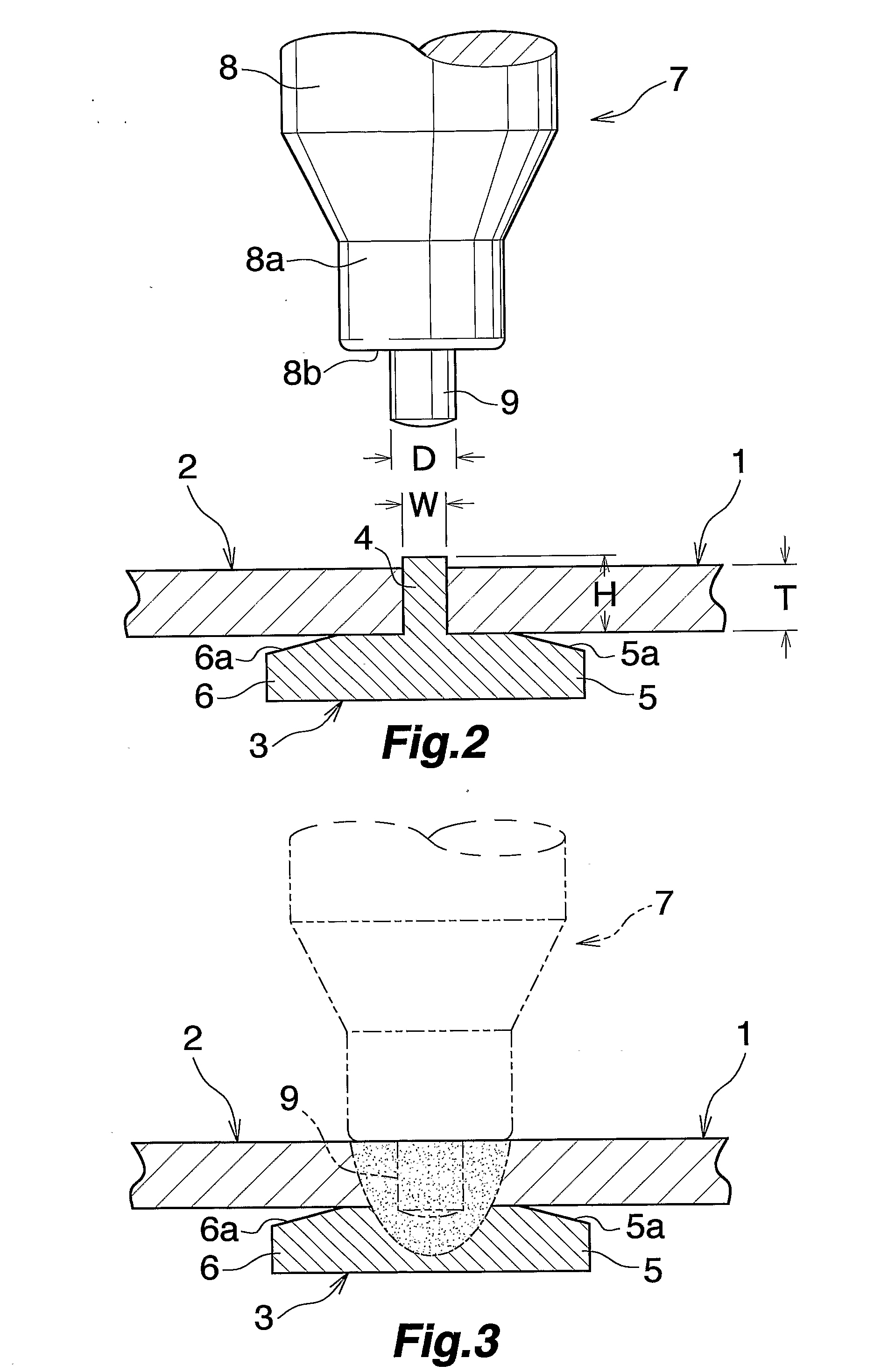
[0049]Two workpieces (1) and (2) formed of JIS A6061-T6 were prepared. The workpieces (1) and (2) had an outside diameter of 200 mm, an inside diameter of 190 mm, and a wall thickness of 5 mm. Also, the support member (3) formed of JIS A6061-T6 was prepared. The support member (3) was configured as follows: the opposite support portions (5) and (6) excluding the tapered portions (5a) and (6a) has an outside diameter of 190 mm and an inside diameter of 160 mm, and the annular, radially outward projection (4) has an outside diameter of 200 mm and a height H of 5 mm as measured from the outer circumferential surfaces of the support portions (5) and (6). The friction stir welding tool (7) prepared was configured as follows: diameter of shoulder portion (8b) as measured on end face of small-diameter portion (8a) of rotor (8): 15 mm; diameter of probe (9): 5 mm; and length of probe (9): 5 mm.

[0050]With the width of the annular, radially outward projection (4) in the axial direction of the...

embodiment 2

[0058]The present embodiment is shown in FIGS. 5 and 6.

[0059]In the present embodiment, butt end portions of two cylindrical workpieces (20) and (21) to be joined are of the same outer circumferential length, and the outer circumferential surfaces of the butt end portions of the cylindrical workpieces (20) and (21) are positioned at the same cylindrical surface. However, the present embodiment differs from Embodiment 1 in the following: the butt end portions of the workpieces (20) and (21) differ from each other in wall thickness and inner circumferential length; the support member (3) has a first support portion (5) on one side of the annular, radially outward projection (4) so as to support, from the inside, the first workpiece (20) having a thin-walled butt end portion; the support member (3) has a second support portion (6) on the other side of the annular, radially outward projection (4) so as to support, from the inside, the second workpiece (21) having a thick-walled butt end...


PUM

PropertyMeasurementUnit
Lengthaaaaaaaaaa
Thicknessaaaaaaaaaa
Widthaaaaaaaaaa

Abstract

A method for friction-stir-welding two hollow workpieces. While open end portions of the workpieces butt each other, and an annular support member supports the butt end portions from the inside, the workpieces are joined together by friction stir welding. An annular, radially outward projection is formed on the entire outer circumferential surface of the support member in an intermediate region along the support member width. Support portions to be fitted into corresponding end portions of the workpieces for support from the inside are formed on the support member at corresponding opposite sides of the annular, radially outward projection. While the support portions are fitted into the workpieces, respectively, and end faces of the workpieces abut the annular, radially outward projection, the butt end portions of the workpieces and the support member are friction stir welded from the outside. Thereby, the hollow workpieces are welded without joint defect.

Description

CROSS REFERENCE TO RELATED APPLICATIONS[0001]This application is an application filed under 35 U.S.C. § 111(a) claiming the benefit pursuant to 35 U.S.C. § 119(e)(1) of the filing date of Provisional Application No. 60 / 598,061 filed Aug. 3, 2004 pursuant to 35 U.S.C. § 111(b).TECHNICAL FIELD[0002]The present invention relates to a method for friction-stir-welding hollow workpieces in order to manufacture metal products for use in various industries.[0003]Herein and in the appended claims, the term “aluminum” encompasses aluminum alloys in addition to pure aluminum.BACKGROUND ART[0004]In order to join abutting open end portions of hollow workpieces, such as tubes or hollow shapes, arc welding, such as MIG or TIG, has been employed. However, when arc welding is used to join heat-treatment-type alloys, such as JIS A6000 family alloys, heat input during welding has caused an impairment in strength, and occurrence of thermal strain in a heat affected zone.[0005]In recent years, in order ...

Claims


Application Information

Patent Timeline
IPC IPC(8): F16L9/02B23K20/12
CPCB23K20/126Y10T428/12292B23K20/128
Inventor NAGANO, YOSHITAKA
Owner SHOWA DENKO KK
Why Eureka
Try Eureka