Apparatus for performing well work on floating platform

a technology for floating platforms and accessories, applied in the direction of sealing/packing, drilling pipes, drilling/well accessories, etc., can solve problems such as problems such as drilling, completing, and producing problems, and achieve the effect of improving the safety and safety of workers

Inactive Publication Date: 2008-05-01
DEVIN INT
View PDF27 Cites 18 Cited by
  • Summary
  • Abstract
  • Description
  • Claims
  • Application Information

AI Technical Summary

Benefits of technology

[0016]An advantage of the present invention includes use of the frame assembly on a floating offshore platform. Another advantage of the present invention is that the frame assembly, sometimes referred to as a tower, can be used to lift and lower various tools and equipment within a working window area of the frame assembly. The type of work includes rigging up and rigging down well intervention devices such as coiled tubing injector heads, lubricators, and blow out preventors. Another advantage is that the apparatus can be simultaneously used on two wells.
[0017]A feature of the present disclosure is the motion compensator system. In the most preferred embodiment, two motion compensators are arranged in opposite planes relative to the frame assembly's center. Another feature is the travel head that is attached to the motion compensator system and that is also attached to a well intervention device such as a wireline lubricator, a coiled tubing injector head, blow out preventor, etc. Yet another feature is that the frame, in the preferred embodiment, is made up of various modules that are structurally stacked to a desired height.

Problems solved by technology

However, in the case of offshore wells, operational problems arise with the floating platforms, including but not limited to the currents, tides, winds and waves creating a constantly changing ocean surface.
Hence, the normal movement of the ocean surface causes drilling, completing, and producing problems in these offshore environments.
One of the common problems encountered by floating offshore platforms is that the floating structure rises and lowers with the oscillation of the ocean surface.
However, this can create significant stresses in the event that the floating platform (or some appurtenance to the platform) is attached to the well (and / or marine riser) since the floating platform rises and lowers with the ocean surface.

Method used


Image

  • Apparatus for performing well work on floating platform
  • Apparatus for performing well work on floating platform
  • Apparatus for performing well work on floating platform

Examples


Embodiment Construction

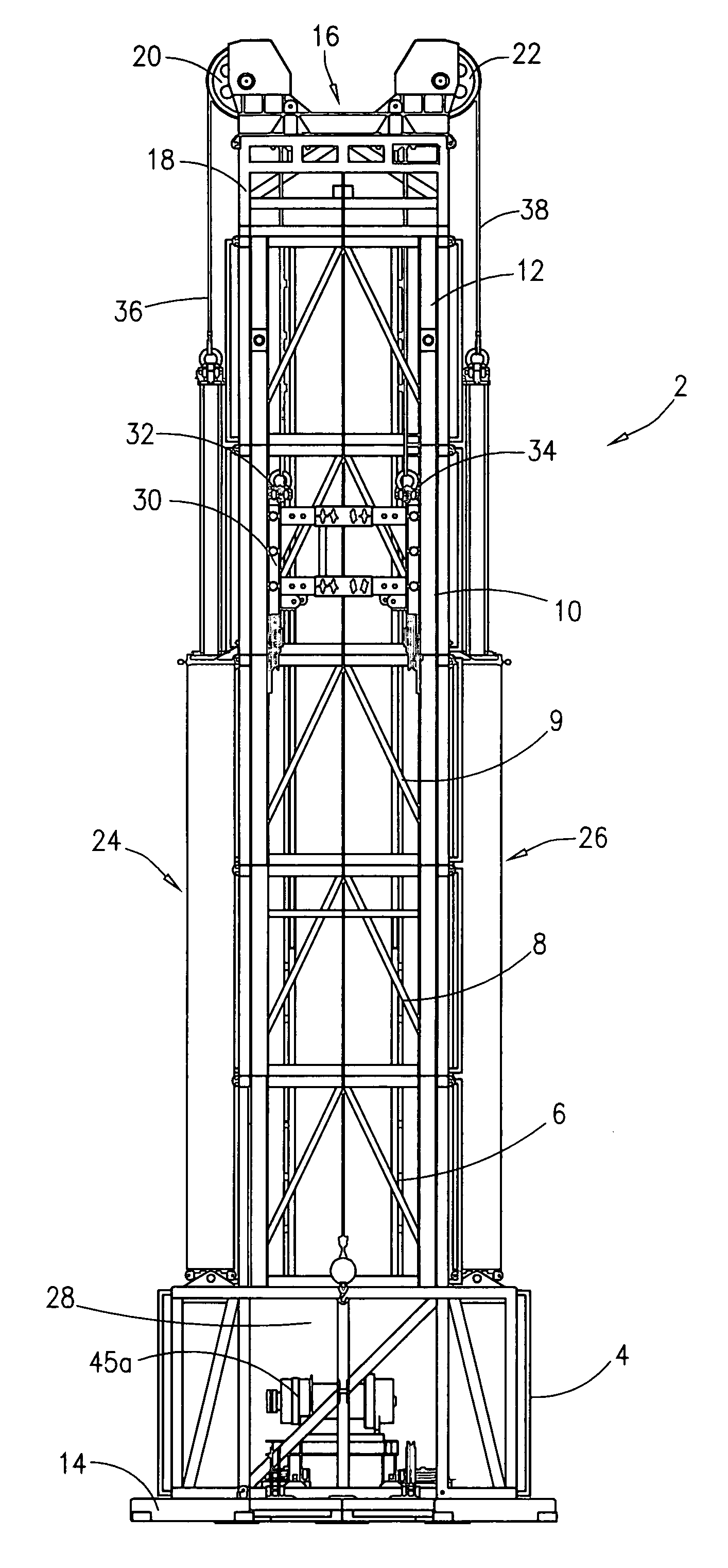
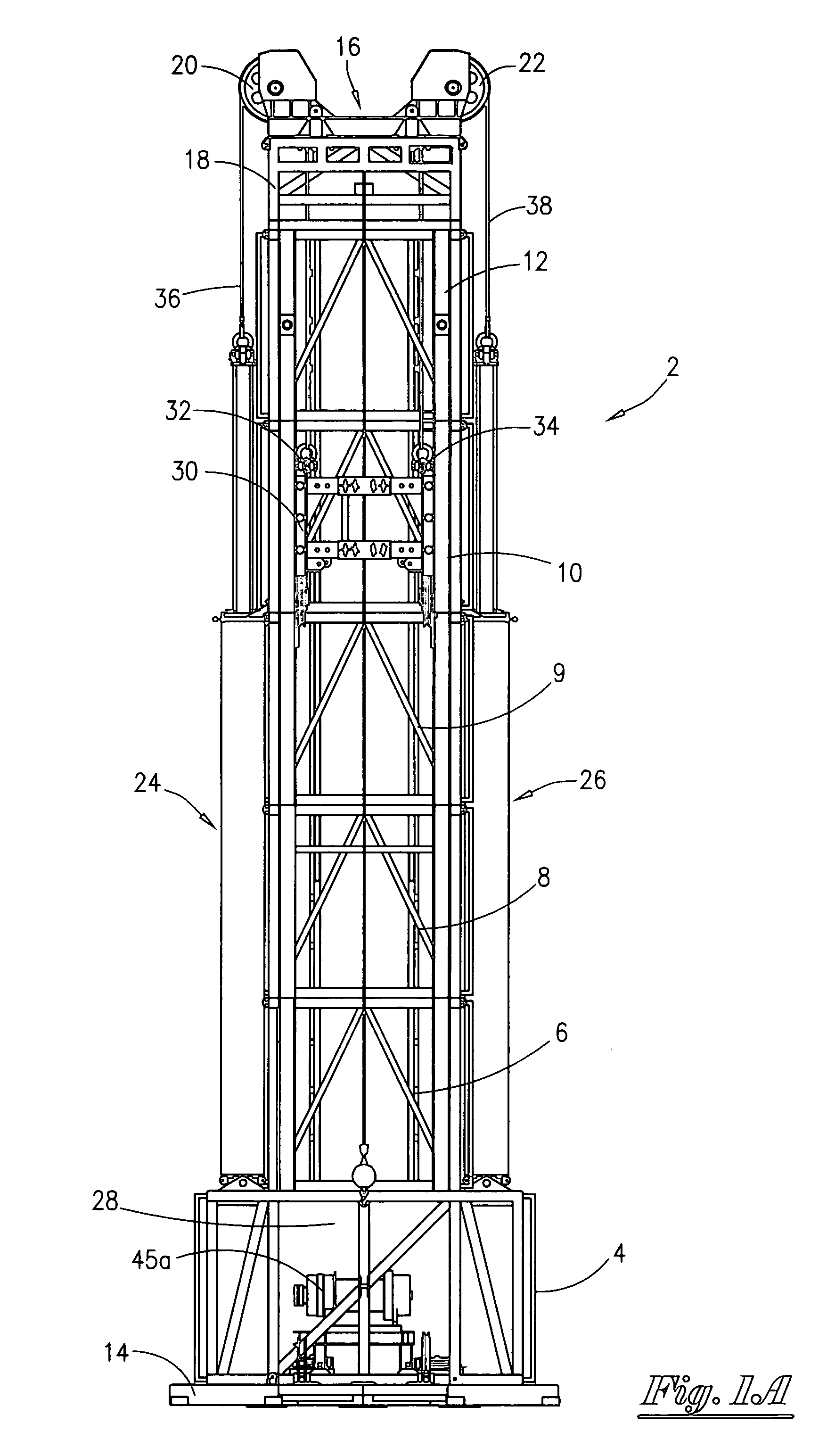
[0029]Referring now to FIG. 1A, a front general layout view of the most preferred embodiment of the well intervention frame assembly 2 will now be described. In the most preferred embodiment, the frame assembly 2 consist of a series of modular frames, sometimes referred to as a tower. As shown in FIG. 1A, the modular frames can be stacked one on top of the other in order to reach a specific height. FIG. 1A depicts the base frame 4, the modular frame 6, the modular frame 8, the module frame 9, the modular frame 10, and the modular frame 12. The modules are commercially available from Devin International Inc. under the name Track Stack Jr. Generally, the individual modular frames have three (3) vertical sides, and wherein one side is open in order to allow a window for entry (sometimes referred to as a working window area). As seen in FIG. 1A, the base frame 4 has a larger footprint (i.e. larger width) in order to better distribute the vertical load which leads to stability of the fra...


PUM


Abstract

An apparatus for supporting a well intervention device connected to a well extending from a floating platform. The apparatus comprises a frame assembly having a first and second end, and wherein the first end is positioned on the platform. The apparatus includes a crown assembly attached to the second end of the frame assembly, a motion compensator member attached to the frame assembly for compensating for vertical movements of the platform, and a travel head having a first connector and a second connector, and wherein the first connector is attached to the compensator member and the second connector attaches the travel head to the well intervention device.

Description

BACKGROUND OF THE INVENTION[0001]This invention relates to an apparatus for performing well work on a floating platform. More particularly, but not by way of limitation, this invention relates to an apparatus for performing well work including a frame assembly with travel head and a method of use on a floating platform.[0002]In the search for hydrocarbons, operators find it necessary to drill and complete wells in exotic locations. For instance, wells are being drilled in oceans wherein the water depth may be several thousand feet. As those of ordinary skill in the art will recognize, the wells are drilled from rigs that are floating on the ocean surface. Once drilled, the wells are completed, and production facilities are installed. During the course of drilling, completing and producing, numerous well intervention techniques must be employed. However, in the case of offshore wells, operational problems arise with the floating platforms, including but not limited to the currents, t...

Claims


Application Information

Patent Timeline
Patent Type & Authority Applications(United States)
IPC IPC(8): E21B29/12
CPCE21B19/09
Inventor MONCUS, JAMES DEVINMILLER, JOSEPH HAYDENDUHON, BRYAN
Owner DEVIN INT
Why Eureka
Try Eureka