Periodic Variation of Velocity of Propagation to Reduce Additive Distortion Along Cable Length

Inactive Publication Date: 2008-05-08
EI DU PONT DE NEMOURS & CO
View PDF6 Cites 49 Cited by
  • Summary
  • Abstract
  • Description
  • Claims
  • Application Information

AI Technical Summary

Benefits of technology

[0023]FIG. 8 shows a graphical representation of return loss vs. frequency for a comparative example and an example of the present invention to show the benefit of the present invention for a cable with a periodic defect.
[0024]While the present invention will be described in connection with a pre...

Problems solved by technology

The primary limitation is in meeting the cable to cable noise immunity sp...

Method used


Image

  • Periodic Variation of Velocity of Propagation to Reduce Additive Distortion Along Cable Length
  • Periodic Variation of Velocity of Propagation to Reduce Additive Distortion Along Cable Length
  • Periodic Variation of Velocity of Propagation to Reduce Additive Distortion Along Cable Length

Examples


example 1

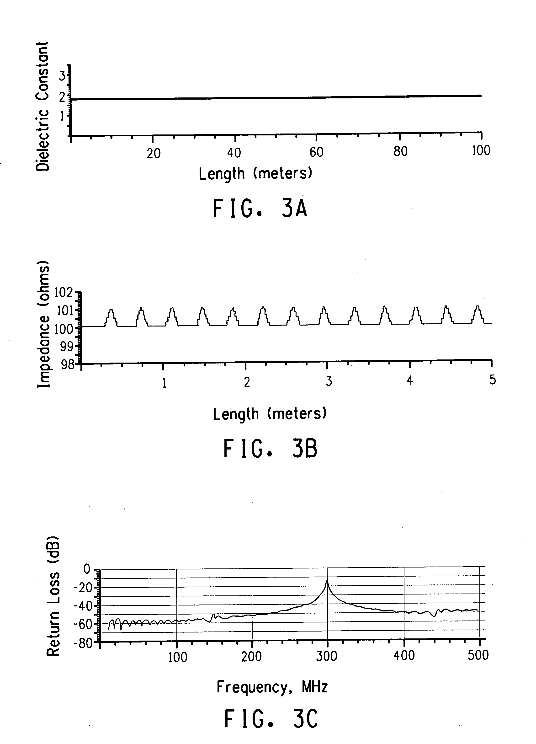
[0081]The impedance of the cable is 100 Ω with a defect magnitude of an additional 1Ω. The total length of the cable is 100 m. The defects are spaced 0.3724 m apart (14.7 inches) which for a dielectric constant of 1.8 should yield a peak in the return loss at 300 MHz.

[0082]A twist (or back twist) applies non-uniform torque to a cable. The spacing of the defects is affected as a function of its location within the cable. The defects at the end of the cable are affected the most moving 1 cm while defects at the center are not affected at all. A linear distribution of the torque would only shift the return loss peak but not affect its height. A non-linear distribution of the torque “smears-out” the peak reducing its height. Table 1 shows modeling data of return loss improvement. In one case the applied periodic variation is triangular in shape. In another, it is sinusoidal in shape.

TABLE 1ReturnReturn LossDielectricTwistLossImpedanceImprovementConstant(cm)(dB)(Ohms)(dB)standard1.8011.9...

example 2

[0087]An example of the present invention is demonstrated by this example. The conditions of the Comparative Example are repeated for this example with the exception that the position of the water bath, used to cool the coated conductor after it exits the extruder, was varied during the coating run. A length of about 30 inches (75 cm)of the coated wire is immersed in the bath. The normal position for the bath is about 1 ft (30 cm) from the point at which the coated conductor exits the extruder coating die. The bath was moved from 6-18 inches (15-45 cm) from the exit point at a frequency of 12-14 sec per cycle. During the cycle approximately 150 ft (45 m) of insulated conductor passes through the bath. This was the wavelength of the variation and corresponds to a frequency of about 5 MHz. The effect was to change the rate of cooling of the coated conductor and thereby affect the rate and extent of shrinkage of the insulation. In this Example insulation diameter varied ±0.001 inch (25...


PUM


Abstract

A communications cable is provided that reduces the additive distortion of intended information encoded as electromagnetic energy that propagates longitudinally along the cable by varying the propagation velocity along its length. The additive distortion is reduced by varying the propagation periodically at a frequency that is lower than the highest frequency at which said electromagnetic energy propagates along said cable.

Description

FIELD OF THE INVENTION[0001]The present invention relates to a communication cable transmitting electromagnetic energy encoded with information. More particularly, the present invention relates to a communication cable that reduces additive lo distortion of intended information encoded as electromagnetic energy during propagation of the electromagnetic energy along the cable by periodically varying the propagation velocity (Vp).BACKGROUND OF THE INVENTION[0002]Category 6 (Cat 6) ethernet cable, traditionally operated up to 1 Gbit / s, does not meet the more stringent electrical specifications for Augmented Cat 6 cable, to be operated up to 10 Gbit / s at distances up to 100 meters. The primary limitation is in meeting the cable to cable noise immunity specification (alien crosstalk), particularly at frequencies from 100 to 500 MHz. As an example, for twist pairs, alien crosstalk is frequency dependent and usually exists between matched twist pairs within neighboring cables. A number of ...

Claims


Application Information

Patent Timeline
IPC IPC(8): H01B11/06G02B6/44H01B7/00H01B11/02
CPCH01B7/0233H01B11/1839H01B11/06
Inventor KENNY, ROBERT D.WILKER, CHARLES
Owner EI DU PONT DE NEMOURS & CO
Why Eureka
Try Eureka