
Cleat-mountable accessory apparatus

a technology of accessory apparatus and clamping plate, which is applied in the direction of machine supports, special-purpose vessels, vessel construction, etc., can solve the problems of reducing stability, reducing stability, and accelerating corrosion or deterioration

Active Publication Date: 2008-05-08
LC WATERSPORTS
View PDF9 Cites 10 Cited by
  • Summary
  • Abstract
  • Description
  • Claims
  • Application Information

AI Technical Summary

Benefits of technology

[0009]A method for coupling a cleat-mounted apparatus to a cleat may comprise one or more of the steps: (a) disposing a first bracket portion about

Problems solved by technology

To screw or a bolt a device to a boat, holes must be drilled into the hull thereby damaging or weakening the boat and further accelerating corrosion or deterioration.
As such railings are commonly tubular in shape, use of a rounded bracket in combination with a rounded bracket results in a support with reduced stability which may not be equipped to handle the mounting of heavy accessories.
However, many of the products currently available for efficiently storing watersports equipment are constructed such that they are only mountable to vertical tow pylons or tow towers.
Watercrafts which do not incorporate such structures are unable to take advantage of the space saving features of these storage apparatus.

Method used


Image

  • Cleat-mountable accessory apparatus
  • Cleat-mountable accessory apparatus
  • Cleat-mountable accessory apparatus

Examples


Embodiment Construction

[0022]Reference will now be made, in detail, to presently preferred embodiments of the invention. Additional details of the invention are provided in the examples illustrated in the accompanying drawings.

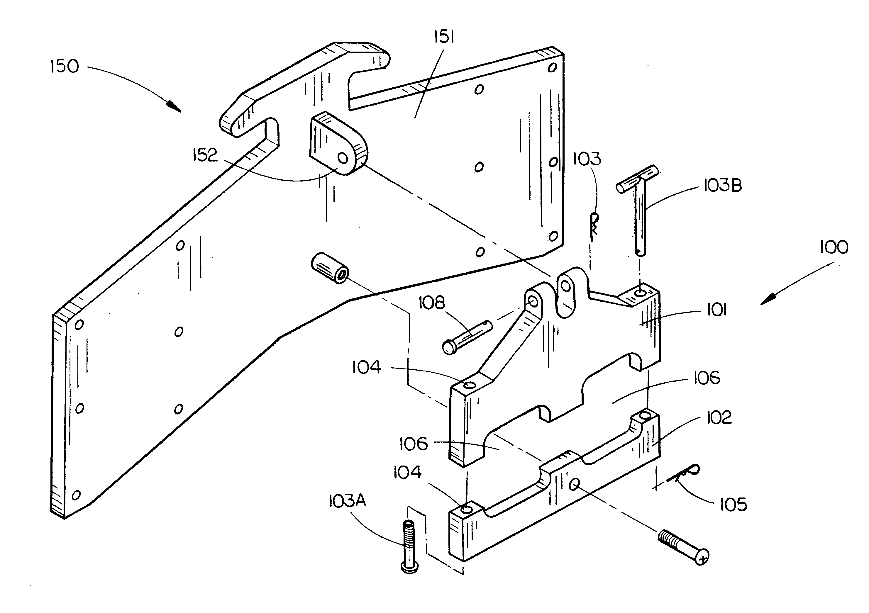
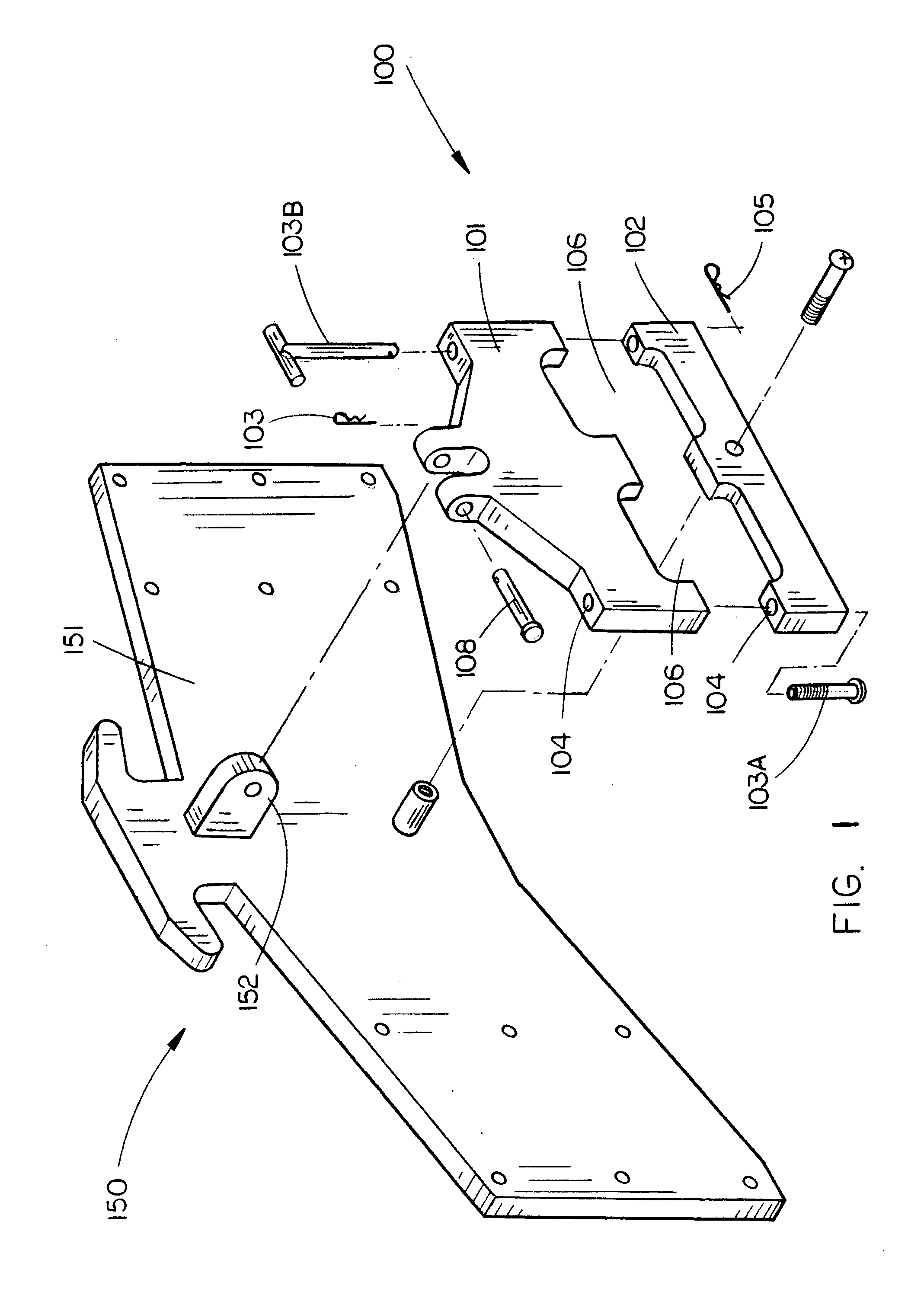
[0023]Referring to FIG. 1, a cleat-mountable support 100 in accordance with an embodiment of the present invention is depicted. The cleat-mountable support may comprise a first bracket portion 101 and a second bracket portion 102. The first bracket portion 101 and second bracket portion 102 may be constructed from sturdy, lightweight, corrosion resistant materials common in the art such as aluminum, fiberglass, carbon-fiber composites, various plastics, and the like.

[0024]The first bracket portion 101 and the second bracket portion 102 may be operably coupled by inserting a bolt 103A or locking pin 103B through apertures 104 in the both bracket portions 101, 102. One or both of the apertures 104 may be threaded so as to cooperatively engage mutually threaded portions of a bolt 103A....


PUM


Abstract

The present invention is directed to an apparatus and a method for coupling an apparatus to a cleat.A cleat-mounted support apparatus in accordance with the present invention may comprise: (a) a first bracket portion; (b) a second bracket portion; and (c) bracket coupling means.A cleat-mountable apparatus in accordance with the present invention may comprise: (a) a cleat-mountable support; (b) an accessory.A method for coupling a cleat-mounted apparatus to a cleat in accordance with the present invention may comprise one or more of the steps: (a) disposing a first bracket portion about a cleat member; (b) disposing a second bracket portion about the cleat member; and (c) operatively coupling the first and second bracket portions.

Description

CROSS-REFERENCE TO RELATED APPLICATION[0001]The present application claims the benefit of U.S. Provisional Application Ser. No. 60 / 856,503, filed Nov. 3, 2006. The present application herein incorporates U.S. Provisional Application Ser. No. 60 / 856,503 by reference in its entirety.BACKGROUND[0002]Considerable design efforts have been applied to the development of boating accessories and their spatial arrangement around the passenger compartments of recreational watercraft. In order to maximize the enjoyment of time spent on the water, it is preferable that boating accessories are located such that they refrain from hindering the movement of occupants while still performing the functions for which they are intended. Currently, there are various means of mounting equipment racks, lamps, audio speakers, and other accessories to a boat.[0003]In some cases, accessory supports will have to be screwed or bolted to the boat hull. To screw or a bolt a device to a boat, holes must be drilled ...

Claims


Application Information

Patent Timeline
IPC IPC(8): B63B17/00
CPCB63B23/62B63B35/7946B63B29/06B63B32/80
Inventor MENNING, JOHNMENNING, JEREE
Owner LC WATERSPORTS
Learn More