Image forming apparatus and control method thereof

a technology of image forming apparatus and control method, which is applied in the direction of electrographic process apparatus, instruments, optics, etc., can solve the problems of image quality problems, pseudo-contours, and inability to control all tones using a single image, and achieve the effect of high image quality

Inactive Publication Date: 2008-05-08
CANON KK
View PDF5 Cites 10 Cited by
  • Summary
  • Abstract
  • Description
  • Claims
  • Application Information

AI Technical Summary

Benefits of technology

[0010]The present invention was accomplished having taken the above described problem of the prior art as a starting point. An object of the present invention is to provide an image forming apparatus that, when forming images using at least one set of developers of the same hue and different tone, forms images having a stabilized high image quality by suppressing a change of hue even when the amounts of applied developers or the like are influenced due to fluctuations in environmental or image forming conditions, and a control method thereof.

Problems solved by technology

The problem thus arises that it is impossible to control all tones using a single image for measurement as described in JPA 2003-228201.
More specifically, because of reproducing a tone of a single color by combining dark toner and light toner, when the stability of reproduction of a high density portion of light toner or a low density portion of dark toner is impaired, problems arise with respect to image quality, such as the occurrence of pseudo-contours.

Method used


Image

  • Image forming apparatus and control method thereof
  • Image forming apparatus and control method thereof
  • Image forming apparatus and control method thereof

Examples


first embodiment

Modify of First Embodiment

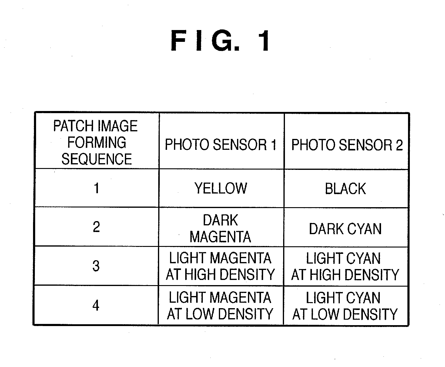
[0095]As modified examples of the first embodiment, as shown in FIG. 8B, it may be possible to form two patch images between image areas in a conveying direction of the intermediate transfer belt 5 by enlarging space area between image areas, though a longitudinal length of the intermediate transfer belt 5 must be longer. In the example of FIG. 8B, patch images of yellow Y, black B, dark magenta M and dark cyan C are formed between the first and second images, and patch images of light magenta m1 (at high density), light cyan c1 (at high density), light magenta m2 (at low density) and light cyan c2 (at low density) between the third and forth images. A number of patch images between image areas in a conveying direction of the intermediate transfer belt 5 may be three or more.

[0096]In FIG. 8C, a image forming sequence of image areas on the intermediate transfer belt 5 and patch images formed between the image areas by the image forming apparatus as shown in ...

second embodiment

Modify of Second Embodiment

[0111]In FIG. 13B, a image forming sequence of image areas on the intermediate transfer belt 5 and patch images formed between the image areas by the image forming apparatus as shown in FIG. 2B is illustrated, according to the second embodiment. A sequence of patch images in FIG. 13B is the same as that of patch images in FIG. 13A by the image forming apparatus as shown in FIG. 2A.

Other Embodiments

[0112]It is to be understood that the object of the present invention may also be accomplished by supplying a system or an apparatus with a storage medium in which a program code of software which realizes the functions of the above described embodiments is stored, and causing a computer (or CPU or MPU) of the system or apparatus to read out and execute the program code stored in the storage medium.

[0113]In this case, the program code itself read from the storage medium realizes the functions of the above described embodiments, and hence the program code and the ...


PUM


Abstract

An image forming apparatus is provided that forms an image using developers of different tone and the same hue. When forming images for measurement for density control, the apparatus performs density control by forming a greater number of density levels of an image for measurement developed using a light developer than the number of density levels of an image for measurement developed using a dark developer. Thus, even if the amount of applied light developer may fluctuate, the fluctuation can be compensated to prevent the occurrence of pseudo-contours that lower image quality.

Description

BACKGROUND OF THE INVENTION[0001]1. Field of the Invention[0002]The present invention relates to an electrophotographic image forming apparatus that includes developers of the same hue and different densities, a control method thereof, and a storage medium, and more particularly to density control of an image forming apparatus.[0003]2. Description of the Related Art[0004]Accompanying the recent advances in image forming apparatuses, the level of needs relating to image quality has also increased. Electrophotographic image forming apparatuses have been proposed in which the number of colors is increased in comparison to the conventional image forming apparatuses that use toners (developers) of four colors, and some of those electrophotographic image forming apparatuses have been put into practical use.[0005]For example, image forming apparatuses exist which add the toner colors of red, blue and green or gold, silver and fluorescent colors to the four conventional toner colors of cyan...

Claims


Application Information

Patent Timeline
Patent Type & Authority Applications(United States)
IPC IPC(8): G03G15/10
CPCG03G2215/00059G03G15/5058G03G15/0131G03G2215/00063
Inventor TOYOHARA, YUICHIRO
Owner CANON KK
Why Eureka
Try Eureka