Relaxation modulus sensor, structure incorporating same, and method for use of same

Active Publication Date: 2008-05-15
NORTHROP GRUMMAN SYST CORP
View PDF14 Cites 9 Cited by
  • Summary
  • Abstract
  • Description
  • Claims
  • Application Information

AI Technical Summary

Benefits of technology

[0014]While the specification concludes with claims particularly pointing out and distinctly claiming that which is regarded as the present invention, the advanta

Problems solved by technology

For example, in order to conventionally test rocket motors for the effects of chemical aging on both the propellant and the rocket motor liner, it is necessary to dissect motors, cut samples of the propellant and l

Method used


Image

  • Relaxation modulus sensor, structure incorporating same, and method for use of same
  • Relaxation modulus sensor, structure incorporating same, and method for use of same
  • Relaxation modulus sensor, structure incorporating same, and method for use of same

Examples


first embodiment

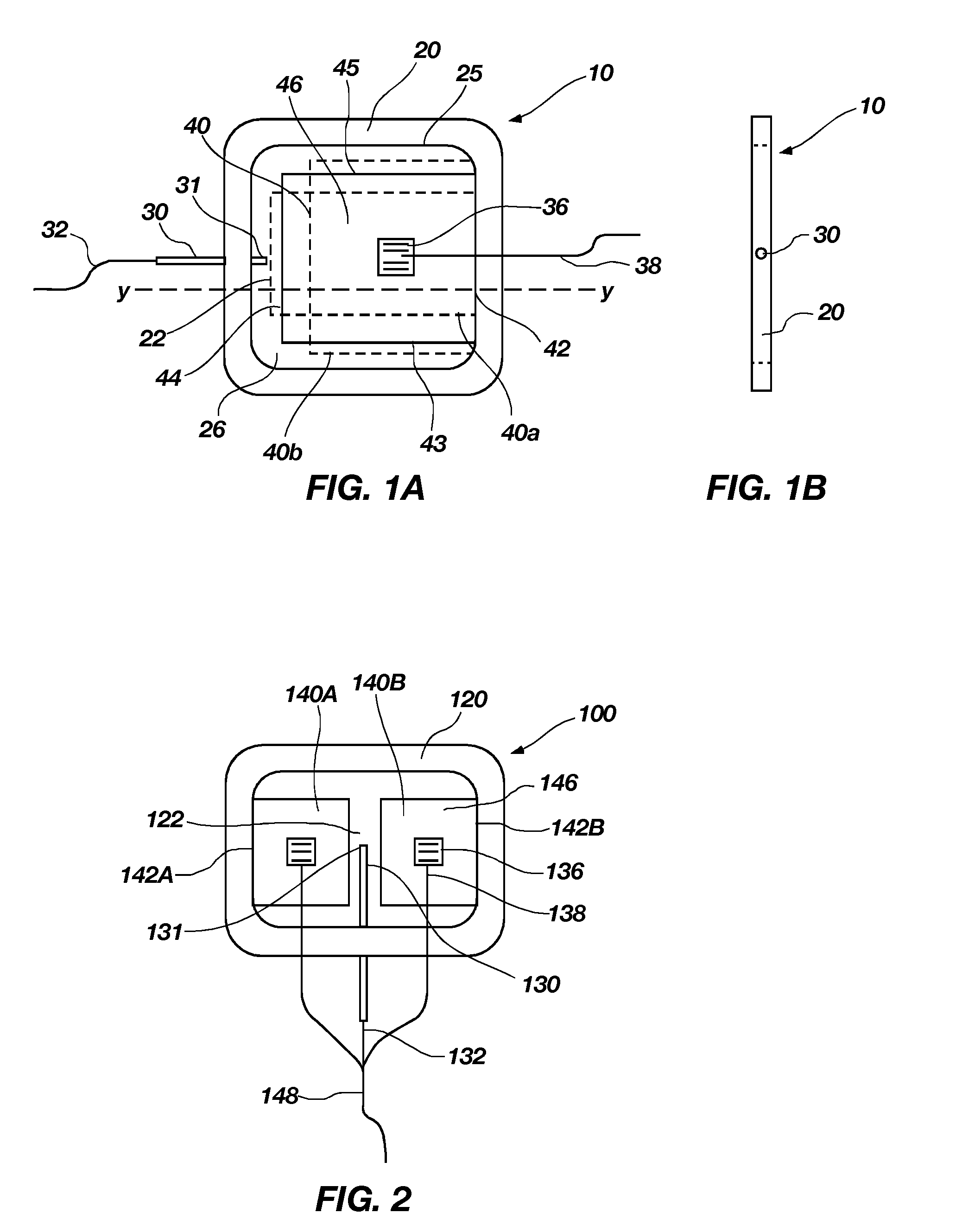
[0026]FIGS. 1A and 1B show a relaxation modulus sensor 10 of the present invention. The relaxation modulus sensor 10 includes a frame 20 with a driver 40 disposed therein. The frame 20 may be, for example, square or rectangular, and include an opening 25 therethrough. The driver 40 may be sized to fit inside of the opening 25 of frame 20. For example, the driver 40 may be square or rectangular, having four sides. The driver 40 may be fixed to the frame 20 by a first side 42 thereof. There may be a separation 26 adjacent each of three sides 43, 44, 45 of the driver 40, between the frame 20 and the driver 40. In one embodiment, the separation 26 may be substantially U-shaped.

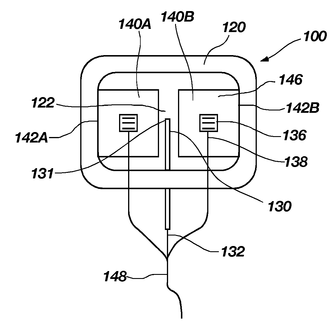
[0027]In use, the sensor 10 may be embedded in a material to be tested, and the material may fill the opening 25 of the frame 20, particularly the separation 26 between the frame 20 and the driver 40. The test material disposed in the separation 26, specifically in a gap 22 between the frame 20 and a second side 4...

third embodiment

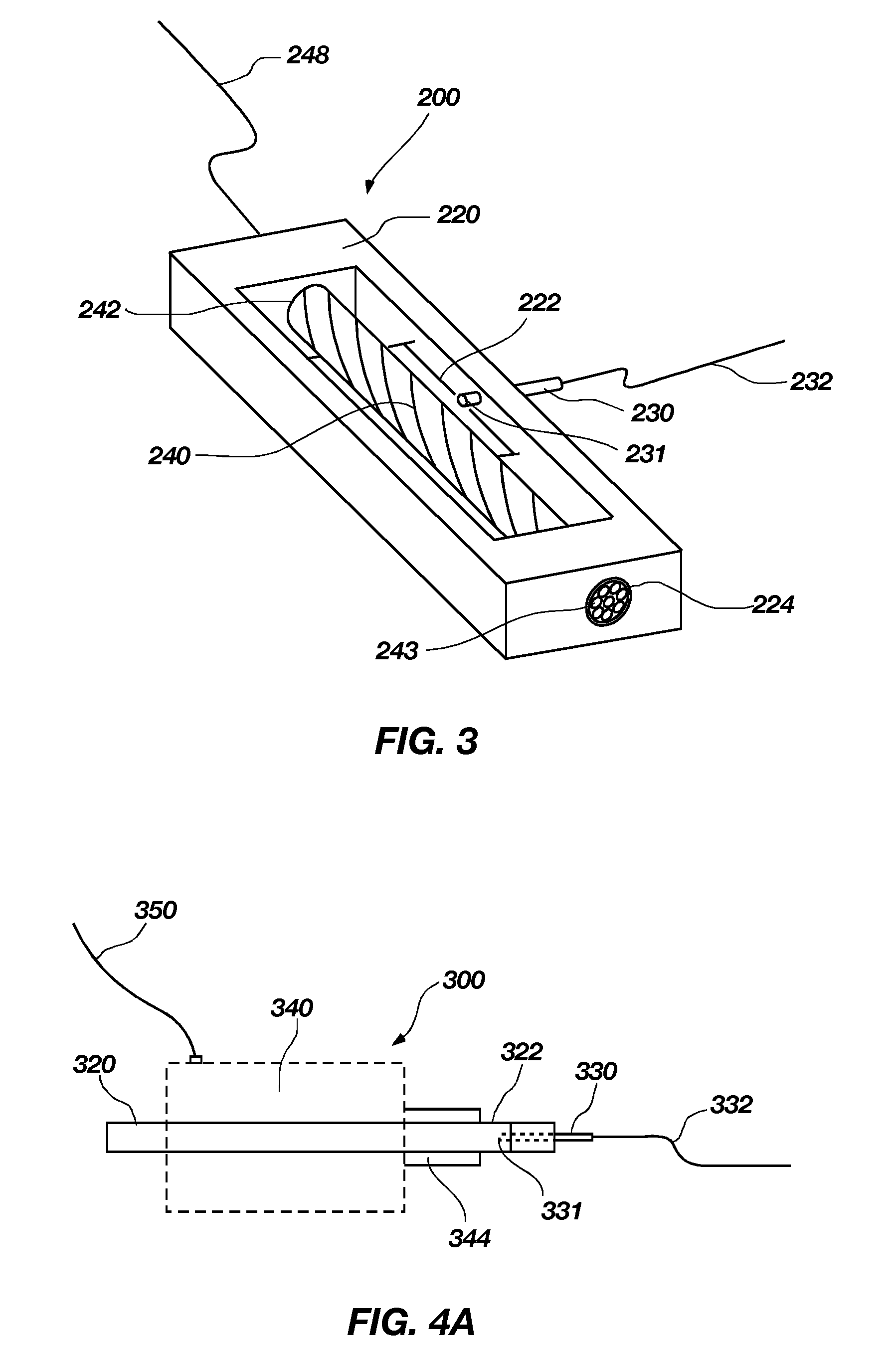
[0038]FIG. 3 illustrates a sensor 200, including a shape metal alloy driver 240 disposed with a frame 220. The shape metal alloy driver 240 may comprise a plurality of shape metal alloy wires or smart wire strands twisted together in an elongated body. A shape metal is a metal which may be stimulated directly with heat or heat generated by electrical resistance to cause deformation, and remembers and returns to its original geometry after the deforming. A shape memory alloy wire reacts when resistance to the electric current in the wire generates heat. The shape metal alloy driver 240 is installed in the opening of a rectangular rigid frame 220 with a first end fixedly attached to the frame 220 and a second end 243 extending through an opening 224 through the frame 220. The opening 224 may be formed, for example, by drilling. The second end 243 is loosely constrained in the opening 224 and is free to rotate when stimulated. A sensing device 230, for example a pressure sensor, is att...

fourth embodiment

[0040]a sensor 300 of the present invention, depicted in FIGS. 4A and 4B, may include a driver 340 having a moveable element 344. The driver 340 may comprise, for example, an electric motor, a hydraulic cylinder, a solenoid, a cam-slider mechanism, a screw actuated ram, or a servo motor with a rod, disk or swing-arm. The moveable element 344 may comprise, for example, a core cylinder of a hydraulic cylinder. The driver 340 may be disposed within a frame 320, with a gap 322 between the moveable element 344 and the frame 320. The moveable element 344 may rotate or move linearly with respect to the frame 320. In use, the sensor 300 may be embedded in a test material (not shown). The moveable element 344 of the driver 340 may be actuated with an electrical current through a conductive line 350, causing a stress in the test material disposed within the gap 322. A pressure sensor 330 is attached to the frame with an active end 331 of sensor 330 disposed in the gap 322. The power and signa...


PUM


Abstract

A sensor for measuring material properties such as the relaxation modulus of a material in situ and a method of measuring material properties of a material are disclosed. The sensor may be substantially embedded in the material, and includes a deformable driver. When actuated, the deformable driver may create a stress in the adjacent material. The movement or deformation of the driver may be measured with a sensing device, for example a strain gage mounted on a surface thereof. The stress in the adjacent material may be measured with a second sensing device, for example a pressure sensor. The measured movement and stress over a predetermined period of time may he used to determine the relaxation modulus of the material.

Description

STATEMENT REGARDING FEDERALLY SPONSORED RESEARCH OR DEVELOPMENT[0001]This invention was made with Government support under Contract No. F04611-03-C-0024 awarded by the Air Force Research Lab. The Government has certain rights in this invention.BACKGROUND OF THE INVENTION[0002]1. Field of Invention[0003]The present invention, in various embodiments, relates to an in situ relaxation modulus sensor for viscoelastic materials, structures incorporating such sensors and a method for use of such a sensor.[0004]2. Discussion of Related Art[0005]The relaxation modulus of a viscoelastic material is a coefficient describing the material's property of releasing or “relaxing” over time when under constant deformation at a constant temperature. Relaxation modulus is a time-dependent material property. The force required to hold a viscoelastic material in constant deformation, while at a constant temperature, diminishes over time. The relaxation modulus of a material is indicative of the mechanica...

Claims


Application Information

Patent Timeline
IPC IPC(8): G01B7/16
CPCG01B7/16
Inventor JOHNSON, MONT A.SHIPLEY, JOHN L.GRAHAM, ROBERTPEARSON, LEE H.
Owner NORTHROP GRUMMAN SYST CORP
Why Eureka
Try Eureka