Travel Control Method For Self-Propelled Carriage

Inactive Publication Date: 2008-05-15
HONDA MOTOR CO LTD
View PDF22 Cites 1 Cited by
  • Summary
  • Abstract
  • Description
  • Claims
  • Application Information

AI Technical Summary

Benefits of technology

[0012]It is an object of the present invention to provide a technique for reducing lateral wobbling caused by the operation of caster wheels in a carriage when a self-propelled carriage comprising the caster wheels is switched back.
[0013]The present inventors focused attention on instances where an operator increases or reduces pressure when using a manual carriage; i.e., presses diagonally forward (usually subconsciously) to turn the caster wheels and prompt smooth turning to result in minimized occurrences of lateral wobbling and vibration. When a control element is added for causing the automatically controlled load-carrying platform to travel slightly diagonally, the caster wheels are able to be turned, and the detrimental lateral wobbling and vibration are able to be minimized.
[0015]According to the thus-arranged control method, the large-scale lateral wobbling and vibration that has conventionally occurred in a self-propelled carriage can be dramatically reduced. Therefore, precision parts and other parts adversely affected by vibration can be transported.

Problems solved by technology

Therefore, precision parts and other parts adversely affected by vibration can be transported.

Method used


Image

  • Travel Control Method For Self-Propelled Carriage
  • Travel Control Method For Self-Propelled Carriage
  • Travel Control Method For Self-Propelled Carriage

Examples


Embodiment Construction

[0023]The embodiments of the present invention are now described below with reference to the accompanying drawings.

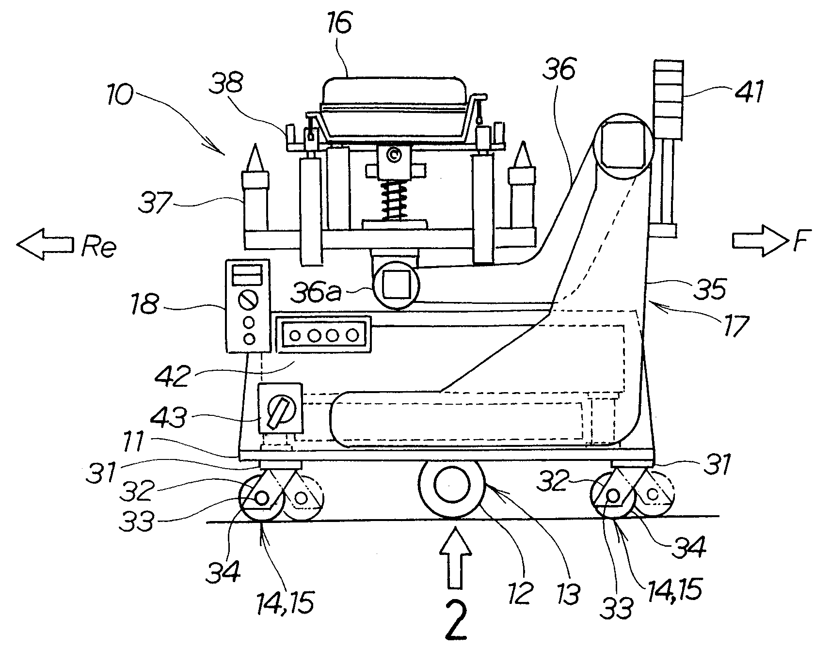
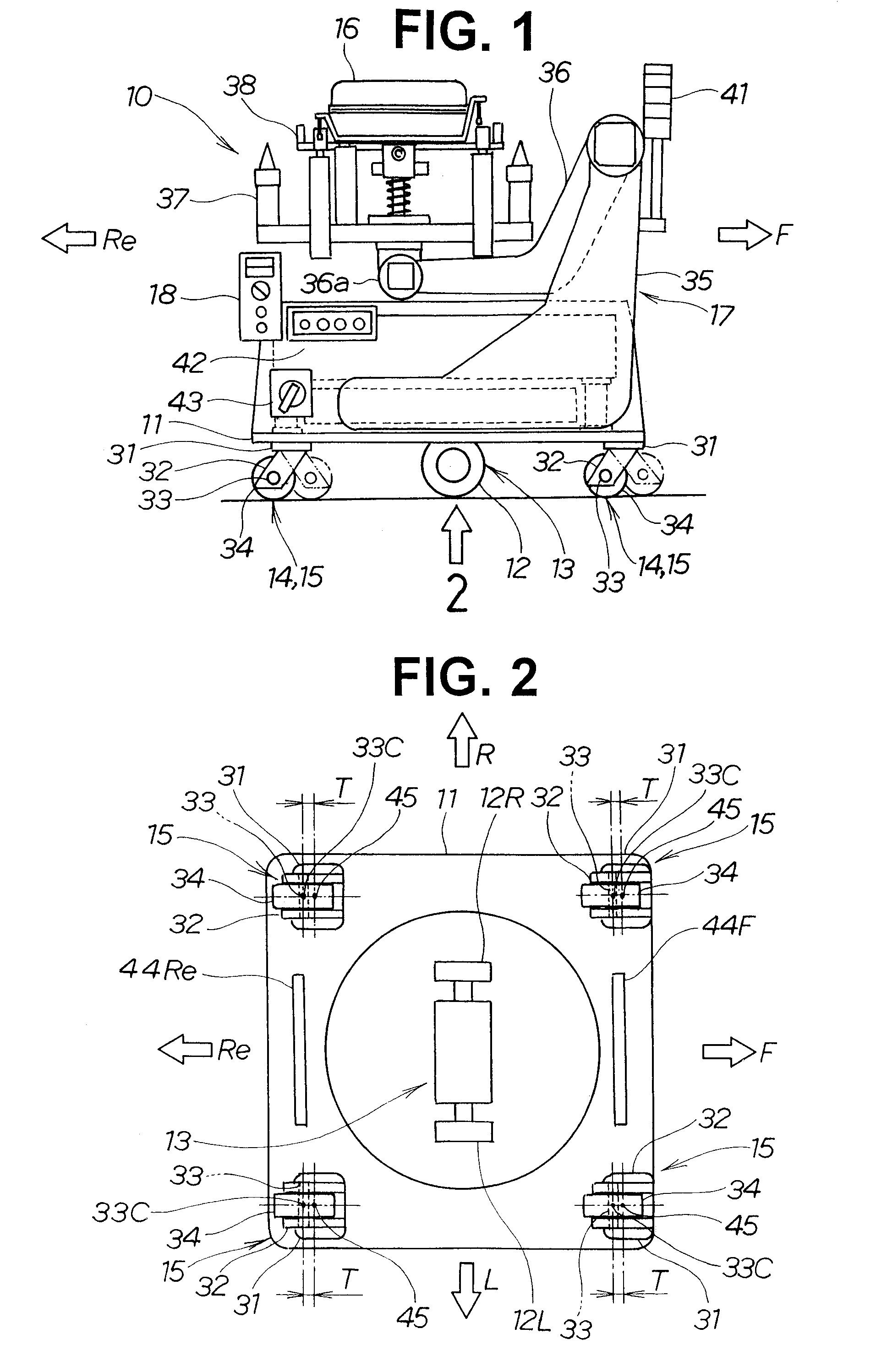
[0024]In FIGS. 1 and 2, a carriage is oriented so that F is a forward direction, Re is a backward direction, R is a rightward direction, and L is a leftward direction; and a carriage 10 is assumed to be in forward movement when working in the forward direction, and in backward movement when working in the backward direction.

[0025]FIG. 1 is a side view of a self-propelled carriage according to the present invention, comprising a caster wheel. The main elements constituting the self-propelled carriage 10 are a platform 11 that doubles as a frame for the carriage; a drive section 13 for driving the carriage 10, with the drive section 13 provided with a drive wheel 12, and mounted to a lower surface of the platform 11; and a caster wheel 15 for supporting the carriage 10, with the caster wheel 15 mounted as a reinforcing wheel 14 to a front and rear of the drive section 13....


PUM


Abstract

A travel control method for a self-propelled carriage having a travel control section for controlling steering-driving wheels. In the method, the steering-driving wheels are steered by a predetermined angle based on a direction change command, and in this state, the carriage is moved forward and backward for a predetermined distance to make the carriage depart from a base line. Then, the carriage is steered toward the base line to return to the base line. After that, the carriage is made to be able to travel along the base line.

Description

TECHNICAL FIELD[0001]The present invention relates to a self-propelled carriage having caster wheels, and to a travel control method for a self-propelled carriage for minimizing lateral wobbling that occurs when a travel direction changes from forward to backward or from backward to forward.BACKGROUND ART[0002]Prior art self-propelled carriages having caster wheels provided to the periphery of steering / driving wheels and configured so that the direction of the self-propelled carriage changes in accordance with changes in a steering direction of the steering / driving wheels have been disclosed in, e.g., Japanese Patent Laid-Open Publication No. 7-257387. A self-propelled carriage shall be described with reference to FIGS. 6, 7A, and 7B hereof.[0003]FIG. 6 is a diagram used to describe a basic configuration of the prior art technology. In a self-propelled carriage 100 (also referred to below simply as a “carriage”), shafts 102, 102 are mounted on a carriage frame 101 in a longitudinal ...

Claims


Application Information

Patent Timeline
IPC IPC(8): B60B19/12
CPCG05D1/0263G05D2201/0216G05D1/0265
Inventor MARUO, MASARUTAKEKUMA, HIDESHI
Owner HONDA MOTOR CO LTD
Why Eureka
Try Eureka