Cooling system with angled blower housing and centrifugal, frusto-conical impeller

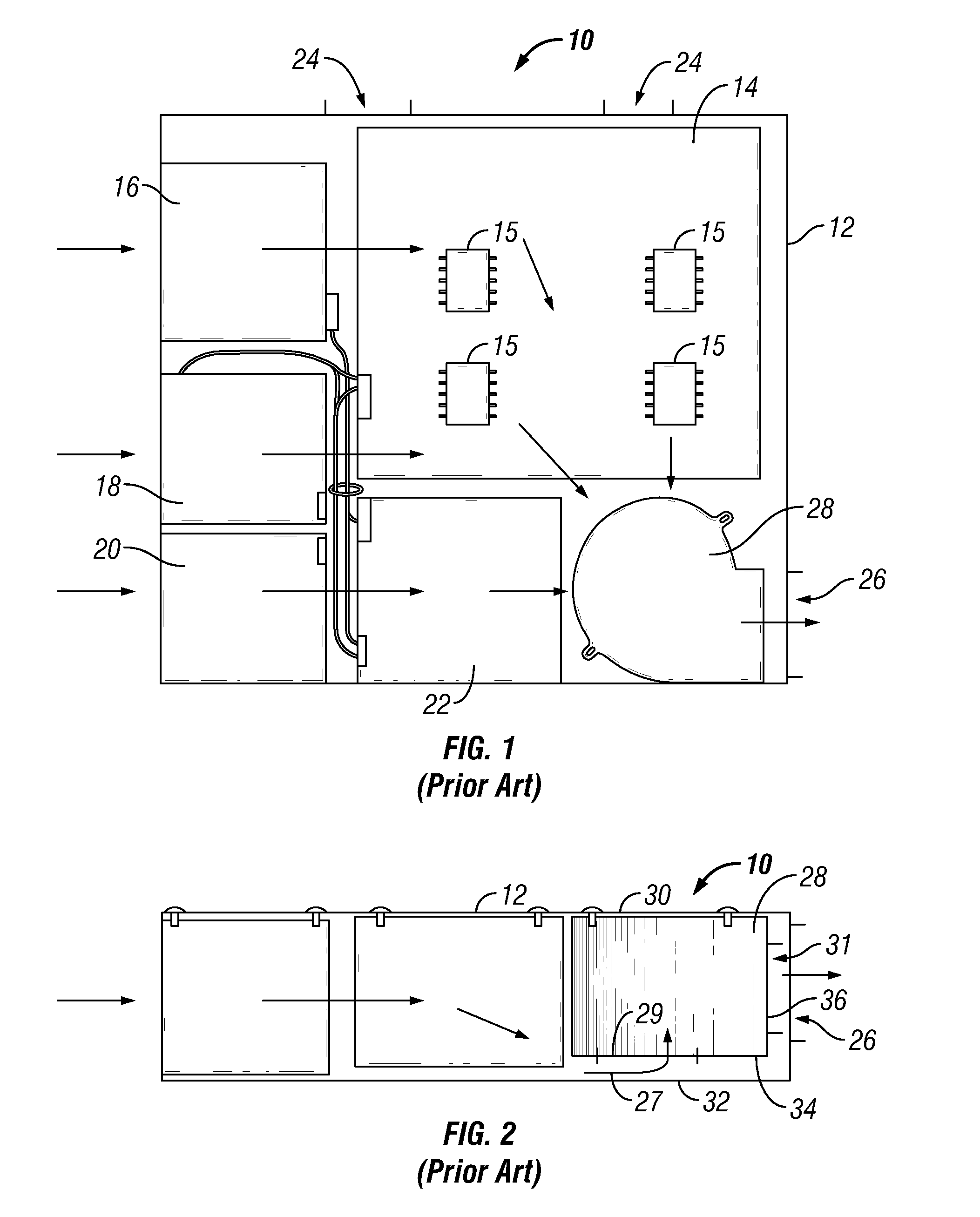
a cooling system and centrifugal technology, applied in the direction of cooling/ventilation/heating modifications, electrical apparatus casings/cabinets/drawers, instruments, etc., can solve the problems of limiting the efficiency of the cooling system, the flow of air is not easy to reach, and the space between the chassis wall is small

Inactive Publication Date: 2008-05-15
IBM CORP
View PDF6 Cites 42 Cited by
  • Summary
  • Abstract
  • Description
  • Claims
  • Application Information

AI Technical Summary

Problems solved by technology

Closely positioning the blower and the blower air inlet to the chassis wall may be required due to compact chassis configurations having limited space.
One drawback of positioning the blower air inlet close to the chassis wall is that there i

Method used


Image

  • Cooling system with angled blower housing and centrifugal, frusto-conical impeller
  • Cooling system with angled blower housing and centrifugal, frusto-conical impeller
  • Cooling system with angled blower housing and centrifugal, frusto-conical impeller

Examples


Embodiment Construction

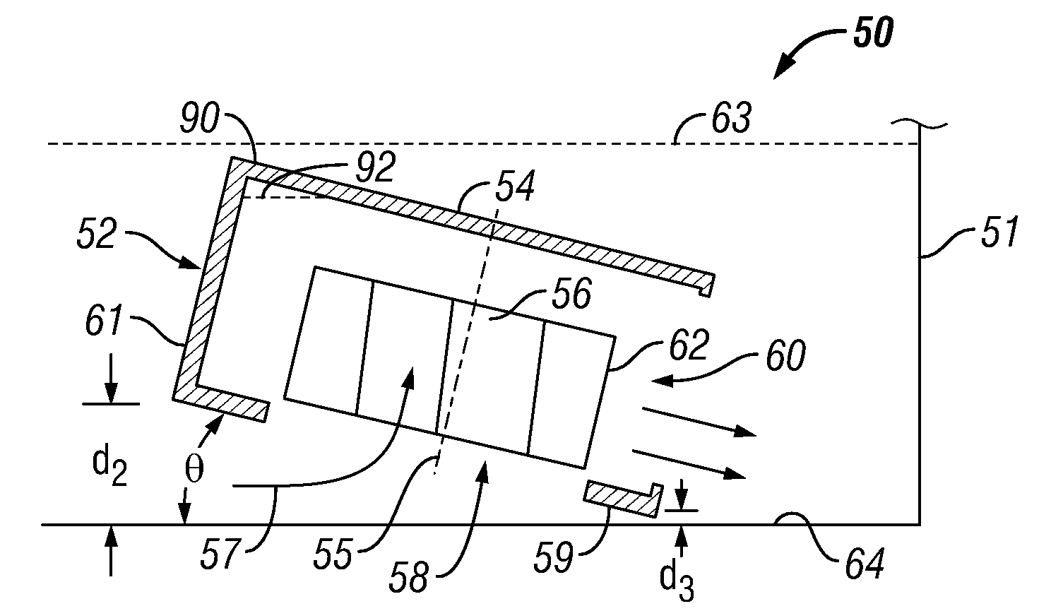
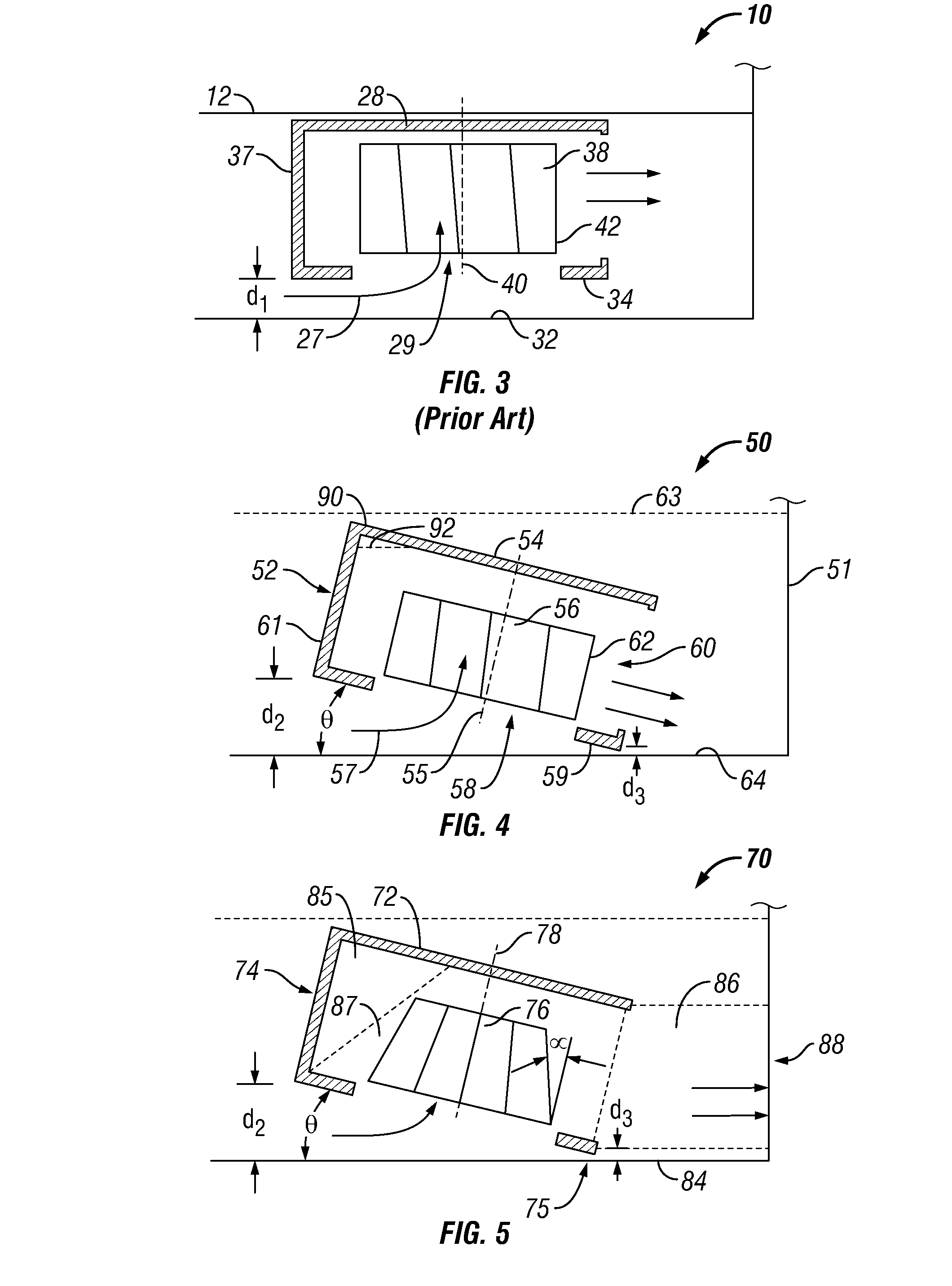
[0016]The present invention provides an improved computer cooling system that is quieter and more efficient than a conventional cooling system. One embodiment includes an improved blower having a frusto-conical, centrifugal impeller disposed in an angled blower housing. More specifically, the blower housing has a blower inlet face that is angled with respect to a facing wall of a computer chassis. The angled blower housing and the frusto-conical profile of the centrifugal impeller both contribute to improved airflow and reduced noise. The angle of the blower housing with respect to the wall of the chassis increases the spacing between the blower air inlet and the wall, and reduces the angle at which airflow must bend to enter the blower air inlet, both of which reduce airflow impedance and increase airflow to the blower. The angle of the blower housing also modifies the blower's acoustic signature to reduce noise level. The frusto-conical profile of the impeller compensates for the ...


PUM


Abstract

An improved cooling system for a computer is disclosed. In one embodiment, the improved cooling system includes an angled blower housing and a frusto-conical, centrifugal impeller. The computer chassis has a chassis air inlet and a chassis air outlet. A blower housing is disposed in the computer chassis. The blower housing has a blower inlet face spaced within 0.512 inches (1.3 cm) from a wall of the computer chassis and facing the wall. A blower air inlet is disposed on the blower inlet face and a blower air outlet is in communication with the chassis air outlet. A centrifugal impeller is rotatably supported in the blower housing about an axis of rotation to move air from the blower air inlet to the blower air outlet. The centrifugal impeller defines a generally frusto-conical profile when rotated about the axis of rotation.

Description

BACKGROUND OF THE INVENTION[0001]1. Field of the Invention[0002]The present invention relates to cooling systems for computers.[0003]2. Description of the Related Art[0004]Computer systems have electronic components that perform various functions and generate heat as a byproduct of electrical resistance. These heat-generating electronic components are typically disposed within a chassis and a cooling system to cool the electronic components. The cooling system generally includes at least one blower for driving airflow through the chassis across the electronic components. A blower may include a blower housing having a blower air inlet, a blower air outlet, and a fan disposed within the blower housing for moving the air through the blower housing from the blower air inlet to the blower air outlet. The blower housing is typically positioned with the blower air outlet in proximity to a chassis air outlet, so that heated air passing through the blower directly exits the computer chassis....

Claims


Application Information

Patent Timeline
IPC IPC(8): G06F1/20
CPCG06F1/20
Inventor JUNE, MICHAEL SEANMEDIIN, BILLY WARRENSTEINKE, MARK EDWARD
Owner IBM CORP
Why Eureka
Try Eureka