Motor assembly for catheter pump

a catheter pump and motor assembly technology, applied in the field of catheter pumps, can solve the problems of high mortality rate, insufficient flow, and inability to advance percutaneously, and achieve the effect of suppressing nois

Active Publication Date: 2014-01-09
TC1 LLC
View PDF2 Cites 156 Cited by
  • Summary
  • Abstract
  • Description
  • Claims
  • Application Information

AI Technical Summary

Benefits of technology

[0018]In one variant, the catheter pump can have a damper disposed between the drive and driven member. The damper can be configured to isolate the drive member or

Problems solved by technology

Heart disease is a major health problem that has high mortality rate.
Fixed cross-section ventricular assist devices designed to provide near full heart flow rate are either too large to be advanced percutaneously (e.g., through the femoral artery without

Method used


Image

  • Motor assembly for catheter pump
  • Motor assembly for catheter pump
  • Motor assembly for catheter pump

Examples


Embodiment Construction

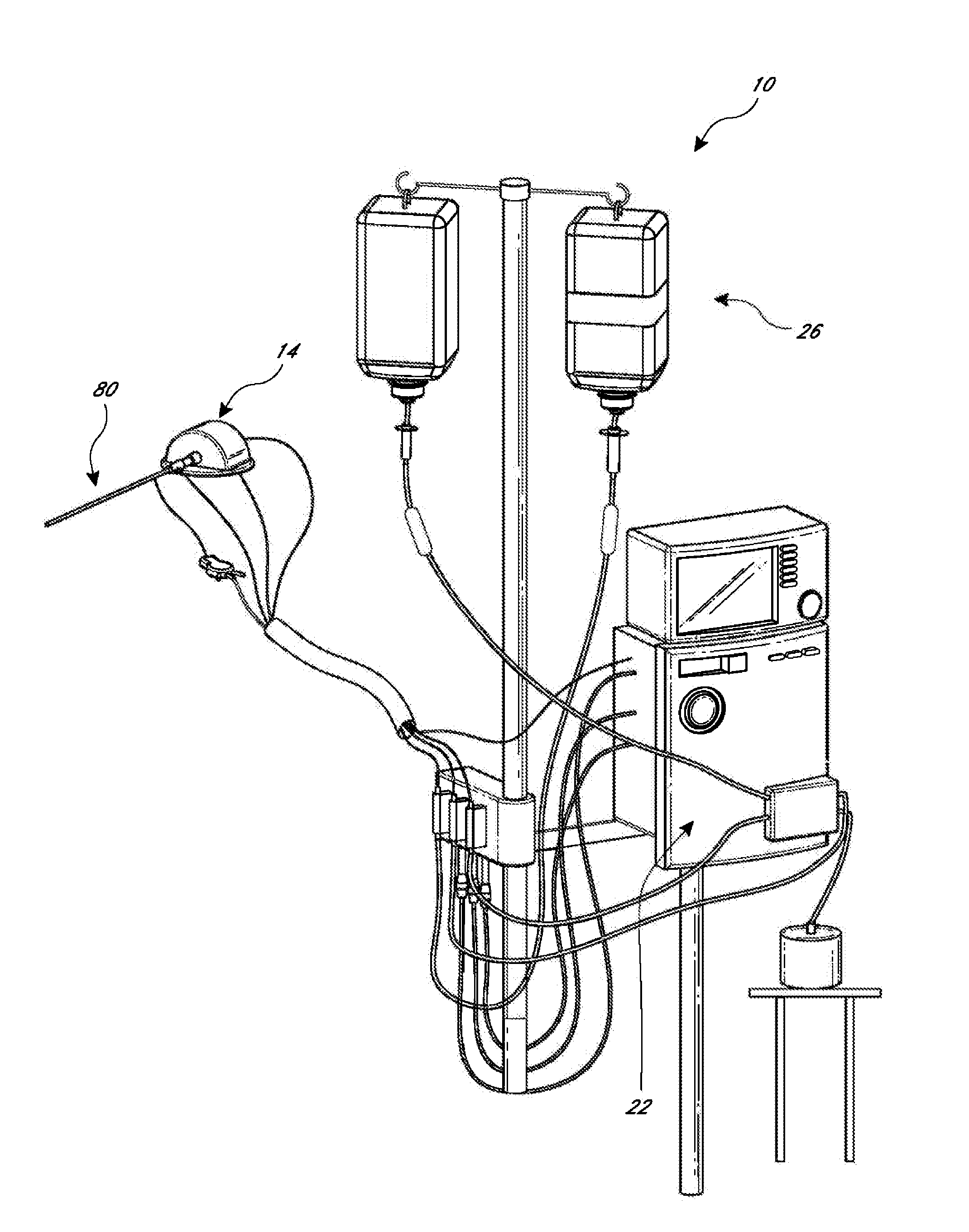
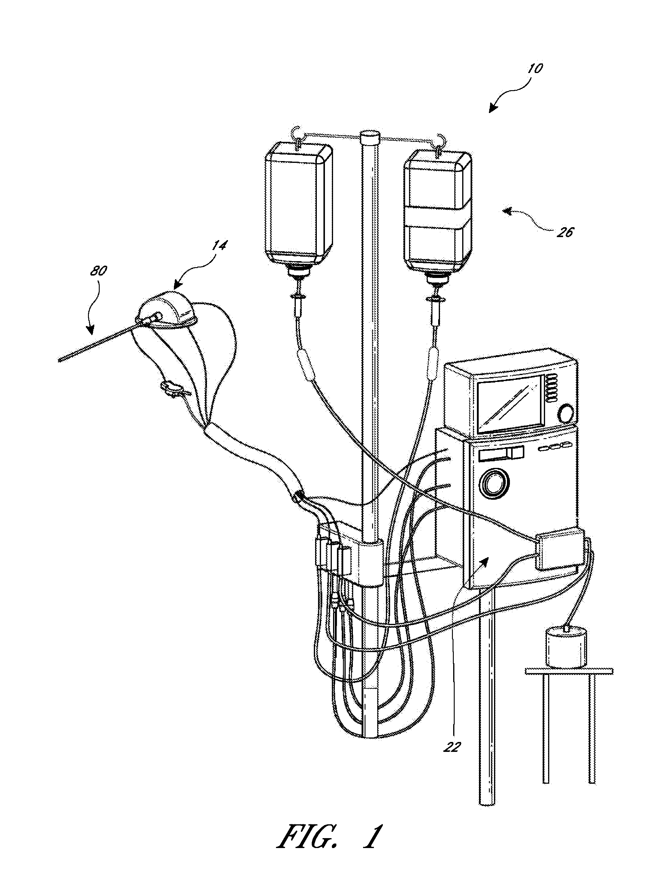
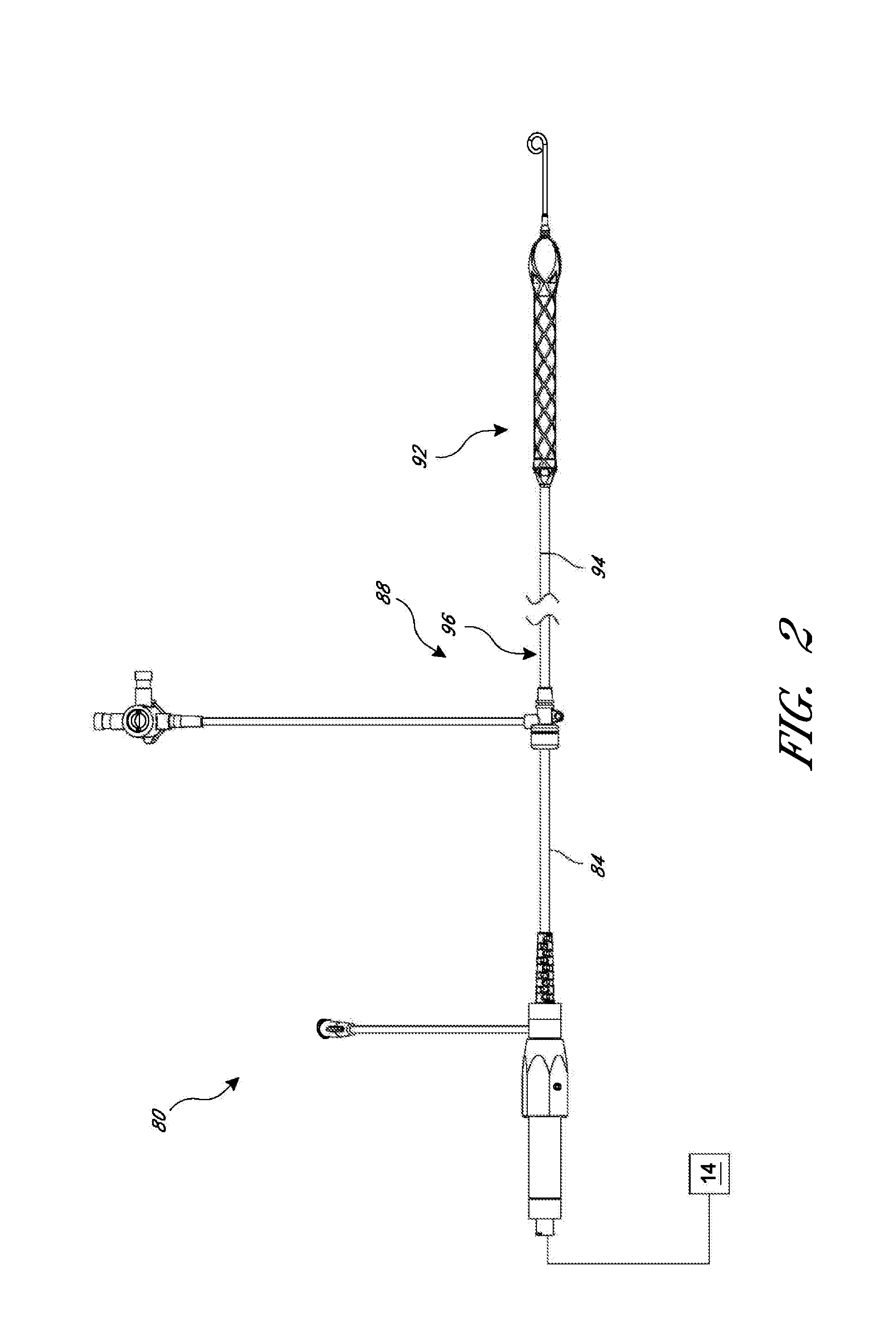
[0042]This application is directed to apparatuses for inducing motion of a fluid relative to the apparatus. For example, an operative device, such as an impeller, can be coupled at a distal portion of the apparatus. In particular, the disclosed embodiments generally relate to various configurations for a motor adapted to drive an impeller at a distal end of a catheter pump, e.g., a percutaneous heart pump. The disclosed motor assembly may be disposed outside the patient in some embodiments. In other embodiments, the disclosed motor assembly can be miniaturized and sized to be inserted within the body. FIGS. 1-3 show aspects of a catheter pump 10 that can provide high performance flow rates. The pump 10 includes a motor driven by a controller 22. The controller 22 directs the operation of the motor 14 and an infusion system 26 that supplies a flow of infusate in the pump 10. A catheter system 80 that can be coupled with the motor 14 houses an impeller within a distal portion thereof....


PUM

PropertyMeasurementUnit
Diameteraaaaaaaaaa
Structureaaaaaaaaaa
Lengthaaaaaaaaaa

Abstract

A catheter pump is disclosed herein. The catheter pump can include a catheter assembly that comprises a drive shaft and an impeller coupled to a distal end of the drive shaft. A driven assembly can be coupled to a proximal end of the drive shaft within a driven assembly housing. The catheter pump can also include a drive system that comprises a motor and a drive magnet coupled to an output shaft of the motor. The drive system can include a drive assembly housing having at least one magnet therein. Further, a securement device can be configured to prevent disengagement of the driven assembly housing from the drive assembly housing during operation of the pump.

Description

INCORPORATION BY REFERENCE TO ANY PRIORITY APPLICATIONS[0001]Any and all applications for which a foreign or domestic priority claim is identified in the Application Data Sheet as filed with the present application, including U.S. Application No. 61 / 667,869, entitled “CATHETER PUMP,” are hereby incorporated by reference under 37 CFR 1.57.BACKGROUND OF THE INVENTION[0002]1. Field of the Invention[0003]This application is directed to catheter pumps for mechanical circulatory support of a heart.[0004]2. Description of the Related Art[0005]Heart disease is a major health problem that has high mortality rate. Physicians increasingly use mechanical circulatory support systems for treating heart failure. The treatment of acute heart failure requires a device that can provide support to the patient quickly. Physicians desire treatment options that can be deployed quickly and minimally-invasively.[0006]Intra-aortic balloon pumps (IABP) are currently the most common type of circulatory suppor...

Claims


Application Information

Patent Timeline
IPC IPC(8): A61M1/12A61M60/13A61M60/216A61M60/422A61M60/515A61M60/538
CPCA61M1/127Y10T29/49236A61M60/414A61M60/13A61M60/808A61M60/216A61M60/865A61M60/88A61M60/422A61M60/538A61M60/515A61M60/419A61M60/148
Inventor TANNER, ADAM R.KEENAN, RICHARD L.MESSNER, DOUG M.BUTLER, MICHAEL R.
Owner TC1 LLC
Why Eureka
Try Eureka