
Thin-type display

Inactive Publication Date: 2008-05-22
CHERNG JYIEH CORP
View PDF4 Cites 28 Cited by
  • Summary
  • Abstract
  • Description
  • Claims
  • Application Information

AI Technical Summary

Benefits of technology

[0005]It is therefore a primary object of the present invention to provide an improved thin-type display in which the position relationship between the support arm and the panel main body is such changed as to facilitate the installation of the transmission interface.
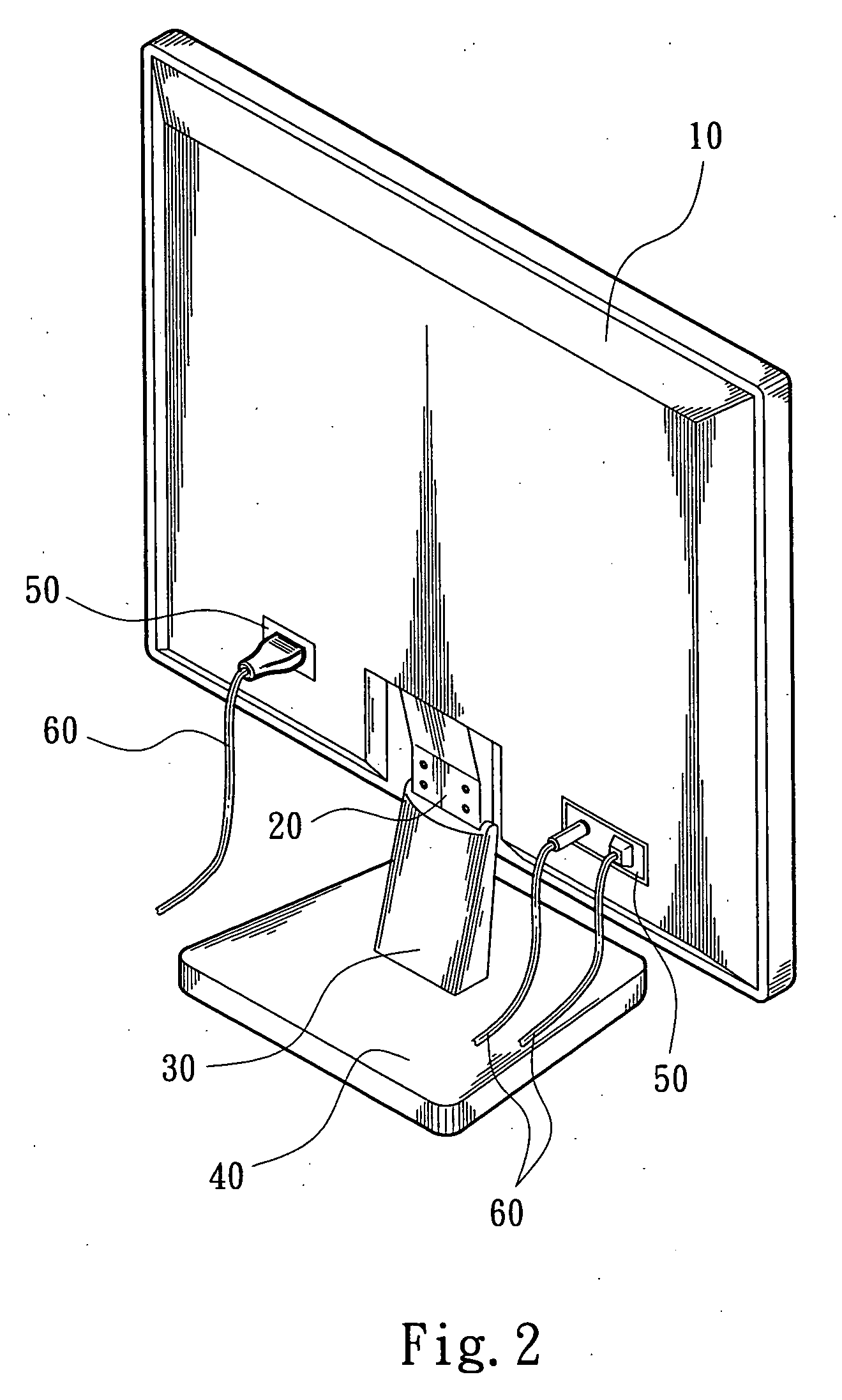
[0006]According to the above object, the thin-type display of the present invention includes: a panel main body having a panel, a frame for accommodating the panel and a transmission interface for receiving signals; a movable bracket having a connecting section fixedly connectable to the back of the panel main body and a fixing section pivotally connected with the connecting section for adjusting the angle of elevation / depression of the panel main body; and a support arm composed of a jacket, a slide member, a leaf spring assembly and a sleeve. The movable bracket is disposed at an upper end of the support arm. A lower end of the support arm is connected with a base. The back face of the frame of the panel main body is formed with a downward extending recessed section. The connecting section of the movable bracket is connected with the panel main body at lower end of the recessed section distal from the transmission interface arranged on the top face of the recessed section. This facilitates the operation and installation and achieves a tidy appearance.

Problems solved by technology

However, when adjusting the elevation of the panel 10, the exposed parts of the transmission lines 60 cannot be shaded by the support arm 30.
This leads to a poor appearance.

Method used


Image

  • Thin-type display
  • Thin-type display
  • Thin-type display

Examples


Embodiment Construction

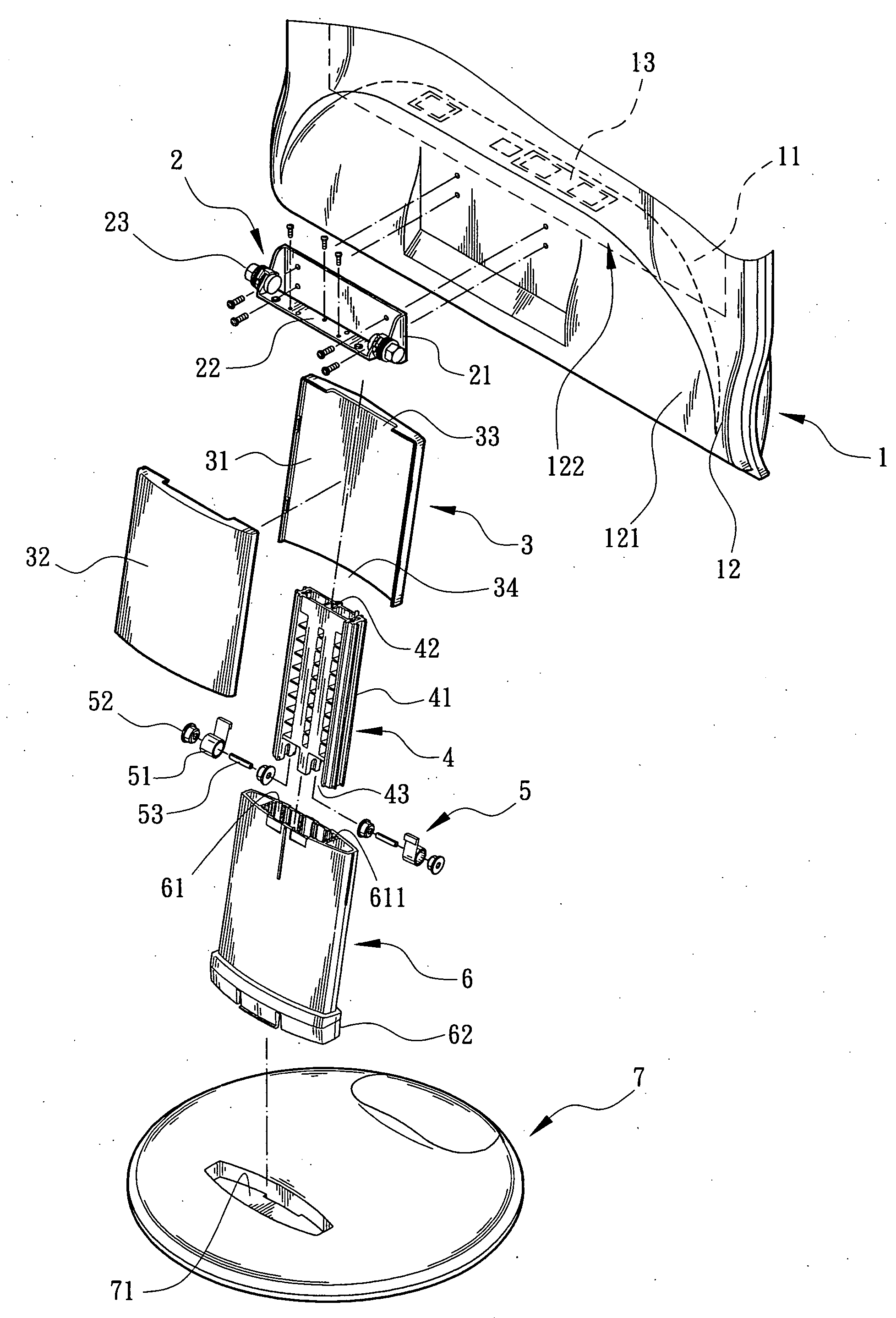
[0014]Please refer to FIGS. 3 and 4. The thin-type display of the present invention includes a panel main body 1 having a panel 11, a frame 12 for accommodating the panel 11 and a transmission interface 13 for receiving signals. The thin-type display of the present invention further includes a movable bracket 2 having a connecting section 21 fixedly connectable to the back of the panel main body 1 and a fixing section 22 pivotally connected with the connecting section 21 via at least one pivot member 23. Accordingly, the connecting section 21 and the fixing section 22 together form an elbow structure for adjusting angle of elevation / depression of the panel main body 1.

[0015]The thin-type display of the present invention further includes a support arm composed of a jacket 3, a slide member 4, a leaf spring assembly 5 and a sleeve 6. In this embodiment, at least one longitudinal guide rib 41 is formed on each of left and right sides of the slide member 4. The slide member 4 is receive...


PUM


Abstract

A thin-type display including: a panel main body having a panel, a frame for accommodating the panel and a transmission interface for receiving signals; a movable bracket having a connecting section fixedly connectable to the back of the panel main body and a fixing section pivotally connected with the connecting section for adjusting the angle of elevation / depression of the panel main body; and a support arm composed of a jacket, a slide member, a leaf spring assembly and a sleeve. The movable bracket is disposed at an upper end of the support arm. A lower end of the support arm is connected with a base. The back face of the frame of the panel main body is formed with a downward extending recessed section. The connecting section of the movable bracket is connected with the panel main body at lower end of the recessed section distal from the transmission interface arranged on the top face of the recessed section. This facilitates the operation and installation and achieves a tidy appearance.

Description

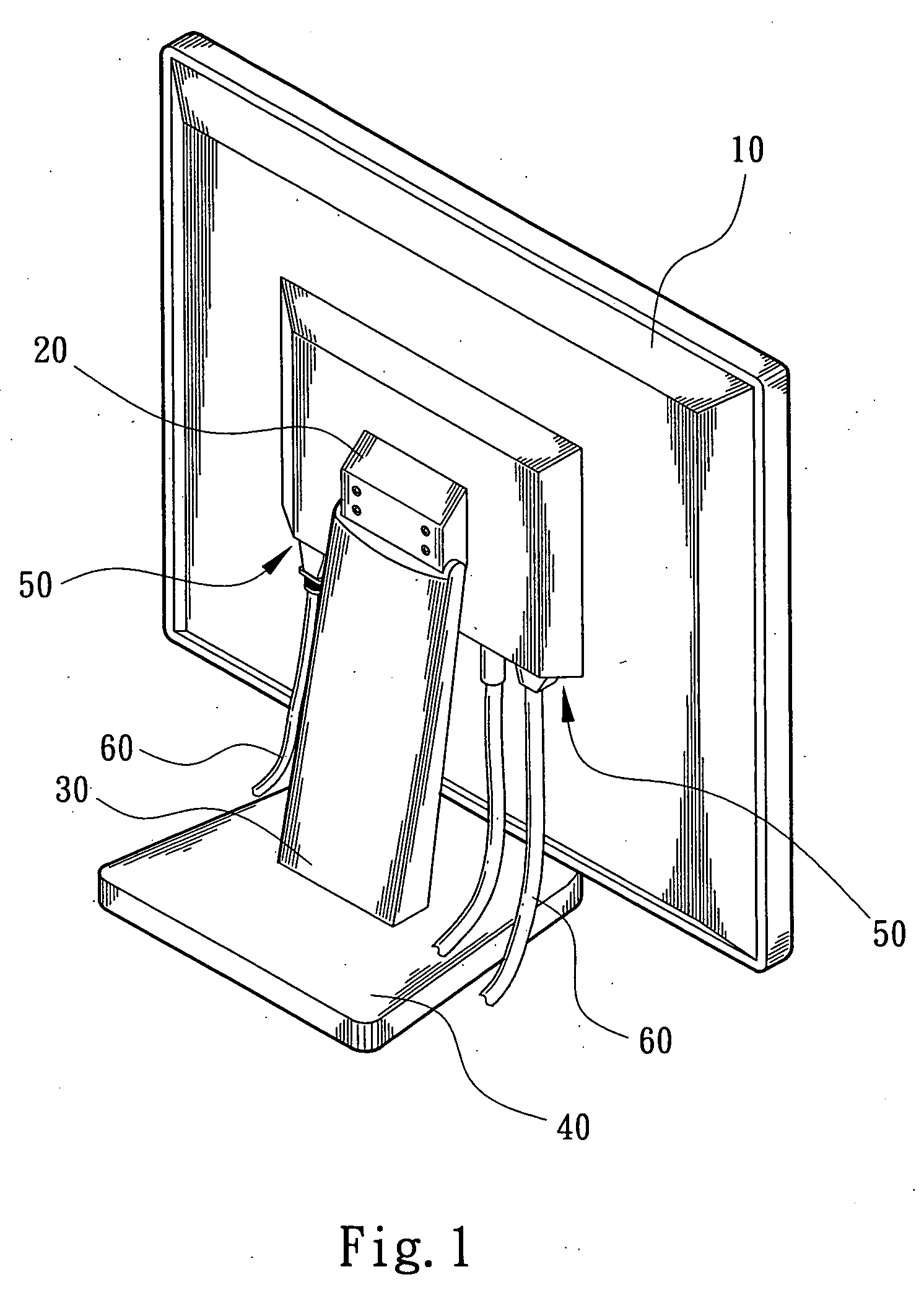
BACKGROUND OF THE INVENTION[0001]The present invention is related to an improved thin-type display in which the posit-ion relationship between the support arm and the panel main body is such changed as to facilitate the installation of the transmission interface. The transmission interface and the support arm will not interfere with each other. In addition, the height of the panel main body is adjustable to shade the support arm and the exposed transmission lines.[0002]FIG. 1 shows a conventional thin-type display including a panel 10, a connecting section 20, a support arm 30 and a base 40 for supporting the panel 10. The connecting section 20 is arranged at the center of the back face of the panel 10 and pivotally connected with the head end of the support arm 30. The support arm 30 substantially upright stands on the base 40.[0003]In the conventional thin-type display, the transmission interface 50 is arranged in a receptacle at the center of the back face of the panel 10. Multip...

Claims


Application Information

Patent Timeline
IPC IPC(8): G06F1/16
CPCG06F1/1601Y10S248/917
Inventor LEE, KUN-SHENG
Owner CHERNG JYIEH CORP
Learn More