
Ergonomic Cushion for a Fishing Rod

a cushion and fishing rod technology, applied in the field of fishing rod improvement, can solve the problems of cushion itself becoming a part of the problem, bruising, soreness,

Inactive Publication Date: 2008-05-29
KEYS CLYDE J +1
View PDF95 Cites 40 Cited by
  • Summary
  • Abstract
  • Description
  • Claims
  • Application Information

AI Technical Summary

Benefits of technology

[0012]The novel cushion is ergonomically designed. It is adapted to be releasably attached to a proximal end of a fishing rod. It includes a top and a bottom that are integrally formed with one another. The top has a width greater than a width of the bottom part and the cushion has a height substantially equal to a combined width of the top and bottom. Accordingly, the cushion fits the contour of an armpit so that a fisherman may place the cushion under his arm for extended periods of time with no loss of blood circulation.
[0015]The throughbore is positioned in close proximity to a bottom wall of the cushion so that substantially all of the cushioning material is positioned between the proximal end of the rod and the under arm of the user, thereby maximizing the cushioning power of the cushioning material.
[0016]The ergonomic shape of the cushion fits the contour of the user's underarm so that the cushion may be comfortably used for long periods of time, with no blockage of blood flow and no numbness.

Problems solved by technology

However, due to the repeated efforts of the fish, the fisherman's underarm area or armpit receives a beating which may lead to bruises, soreness, and the like.
Although this earlier device performs its intended function, it has the drawback that is does not fit well under the arm of the fisherman.
The cylindrical shape does not conform to the shape of the armpit and as a result the cushion itself can become a part of the problem.
Thus, half of the cushion provides no cushioning effect because it is not positioned between the armpit and the rod.
The earlier devices in this field also interfere with the placement of the rod butt into a rod holder, i.e., they must be removed from the rod before the rod holder can be used.

Method used


Image

  • Ergonomic Cushion for a Fishing Rod
  • Ergonomic Cushion for a Fishing Rod
  • Ergonomic Cushion for a Fishing Rod

Examples


Embodiment Construction

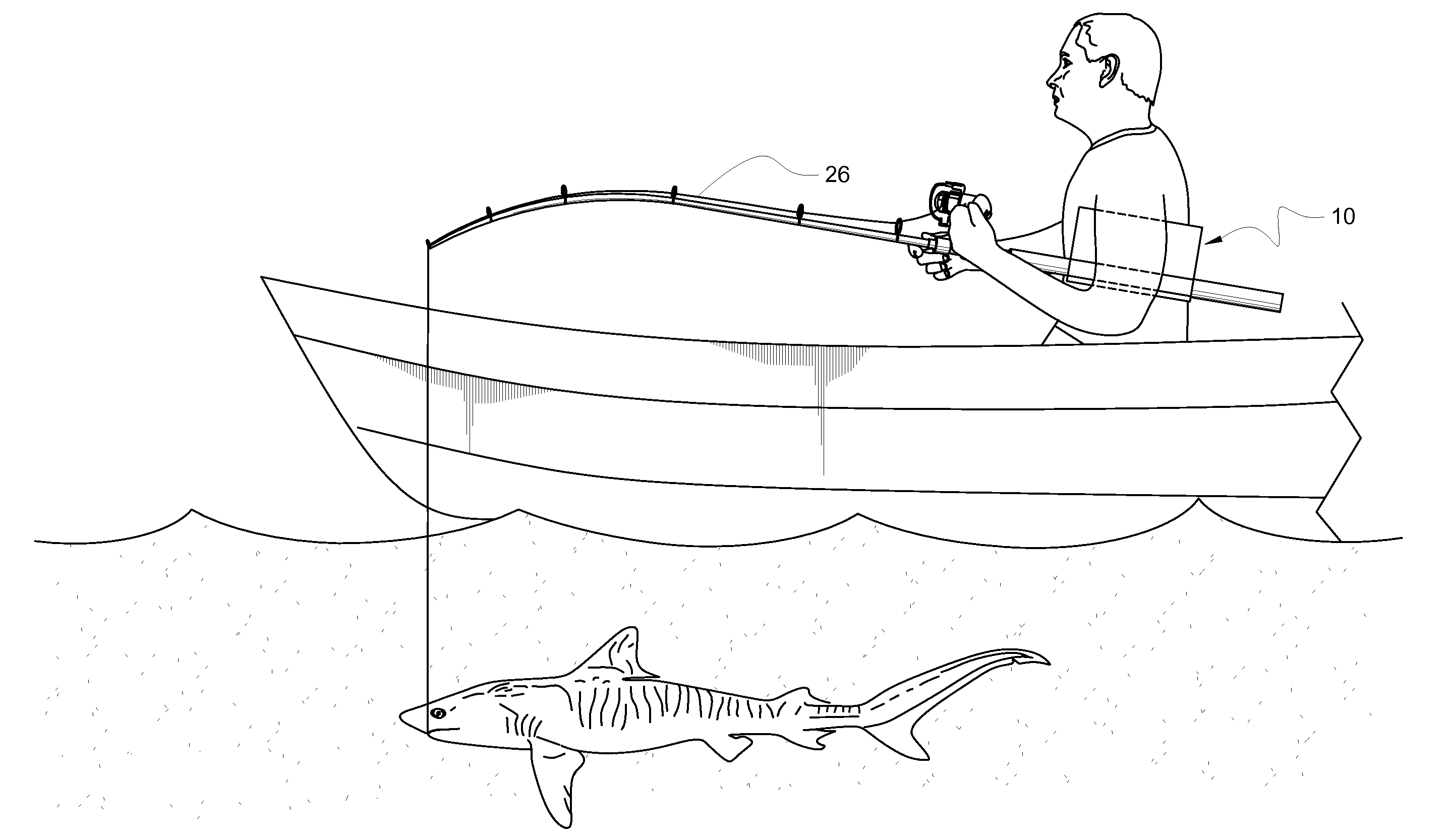
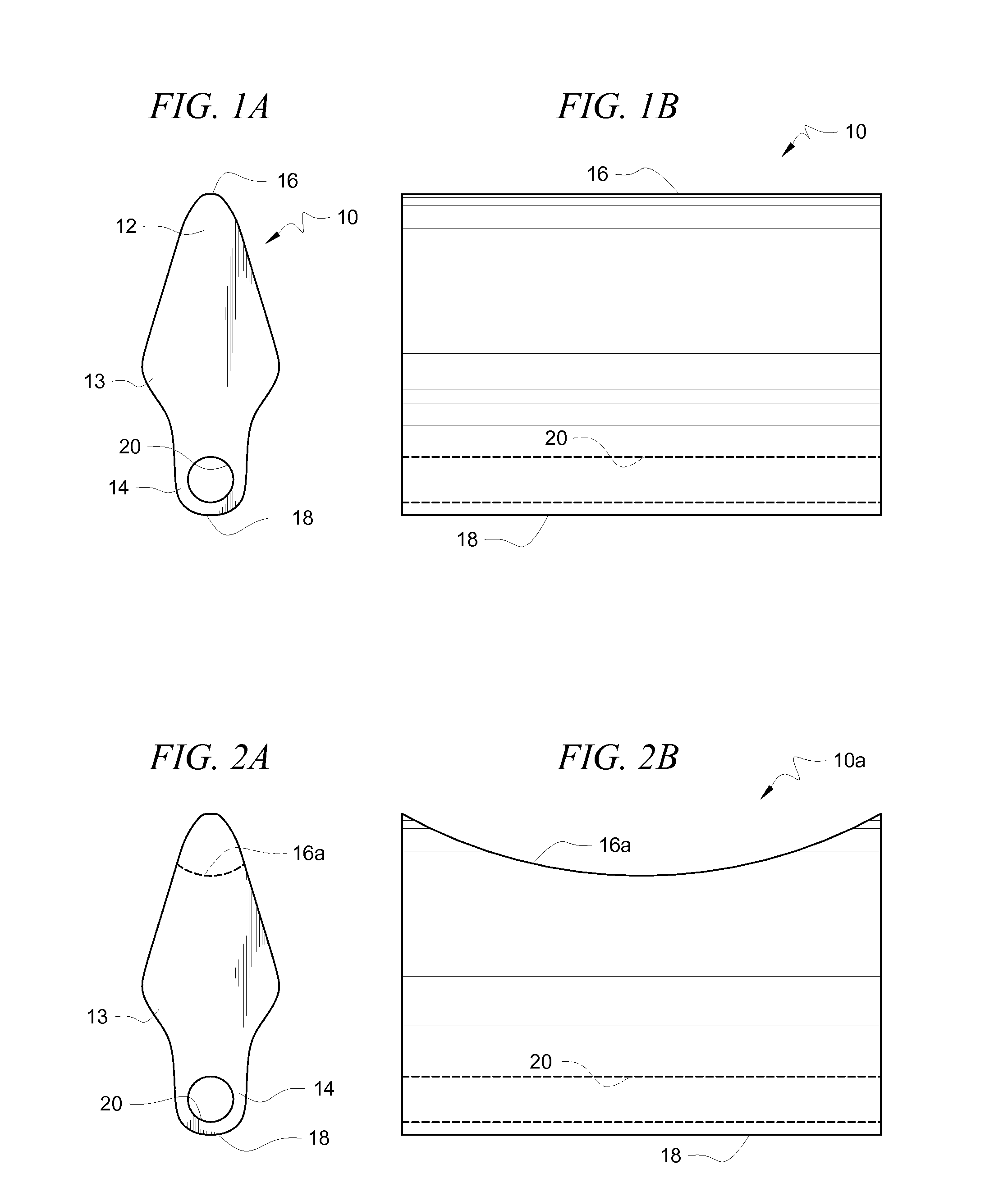
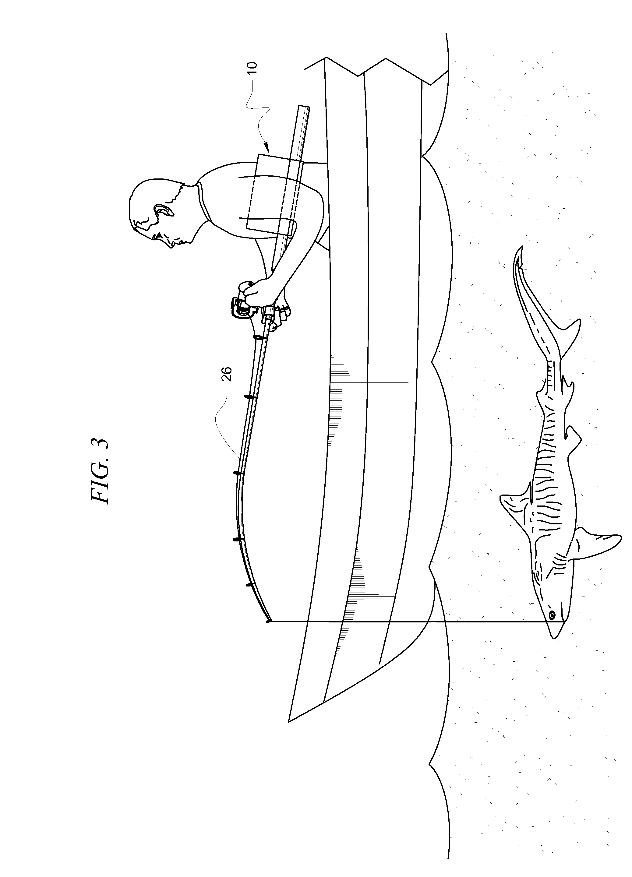
[0026]Referring now to FIGS. 1A and 1B, it will there be seen that the preferred embodiment is denoted as a whole by the reference numeral 10.

[0027]Cushion 10 is formed of any suitable foam. The material is preferably buoyant so that it will float if dropped into a body of water. The material must be resilient so that it quickly returns to its original shape when an external force is removed from it.

[0028]Cushion 10 has a top 12, a middle 13, and a bottom 14 that are integrally formed with one another. Top wall 16 is rounded as is bottom wall 18. Top 12 has a width less than a width of middle 13 and the width of the middle section is greater than the width of bottom 14. The general shape of cushion 10 is irregular but somewhat oval, being widest at its mid-section as aforesaid and having a length greater than its widest part.

[0029]Throughbore 20 is formed in bottom part 14 and extends the entire length of cushion 10 as best understood by comparing FIGS. 1A and 1B. The diameter of th...


PUM


Abstract

An ergonomic cushion is adapted to be releasably attached to a proximal end of a fishing rod. The cushion has a top and a bottom that are integrally formed with one another. The top is wider than the bottom so that the cushion fits under an arm without cutting off circulation. A bore formed in the bottom snugly receives the proximal end. In a second embodiment, the cushion is solid and an elastic band tightly ensleeves the cushion and the proximal end of the rod so that all of the cushion is between the proximal end and the under arm area of the user. The butt end of the rod may be placed into a rod holder without removal of the cushion.

Description

BACKGROUND OF THE INVENTION[0001]1. Field of the Invention[0002]This invention relates to improvements in fishing rods. More particularly, it relates to a cushion that is secured to the proximal end of a fishing rod to absorb impacts generated by certain types of fishing activities.[0003]2. Description of the Prior Art[0004]Grouper and other very large fish are commonly found near the bottom of the body of water within which they live. Thus, fishing for such fish is commonly referred to as bottom fishing. Due to the weight and strength of such large fish, the fisherman usually tucks the proximal end of the fishing pole under his or her arm in order to prevent the distal end of the rod from being pulled downwardly by the fish. However, due to the repeated efforts of the fish, the fisherman's underarm area or armpit receives a beating which may lead to bruises, soreness, and the like.[0005]One inventor addressed this problem by mounting a cylindrical cushion at the proximal end of the...

Claims


Application Information

Patent Timeline
IPC IPC(8): A01K97/10A01K97/00
CPCA01K87/08Y10T16/44Y10T16/476Y10T16/469
Inventor KEYS, CLYDE J.GAUSE, GUNNAR
Owner KEYS CLYDE J
Learn More