Shock suppressor

a technology of shock suppressor and shock energy, which is applied in the direction of shock proofing, machine supports, other domestic objects, etc., can solve the problems of not efficiently dissipating shock energy in vertical or multiple directions, and suppressors can only dissipate shock energy

Inactive Publication Date: 2008-05-29
TSAI CHONG SHIEN
View PDF21 Cites 19 Cited by
  • Summary
  • Abstract
  • Description
  • Claims
  • Application Information

AI Technical Summary

Benefits of technology

[0007]To overcome the shortcomings, the present invention tends to provide a shock suppressor to mitigate or obviate the aforementioned problems.

Problems solved by technology

However, the conventional shock suppressor can only dissipate shock energy in a horizontal direction, but does not efficiently dissipate shock energy in vertical or multiple directions.

Method used


Image

  • Shock suppressor
  • Shock suppressor
  • Shock suppressor

Examples


first embodiment

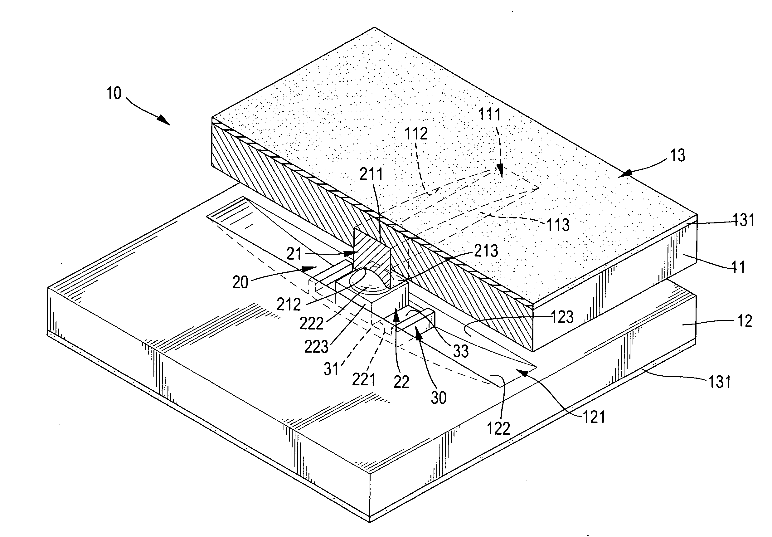
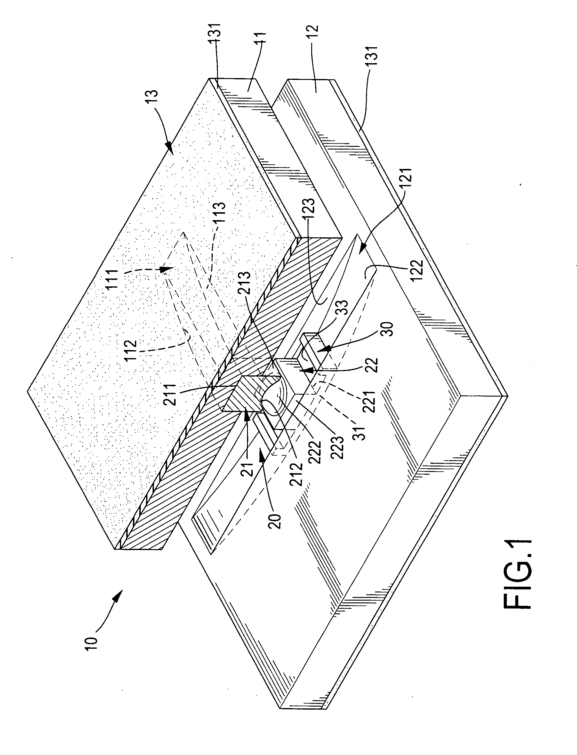
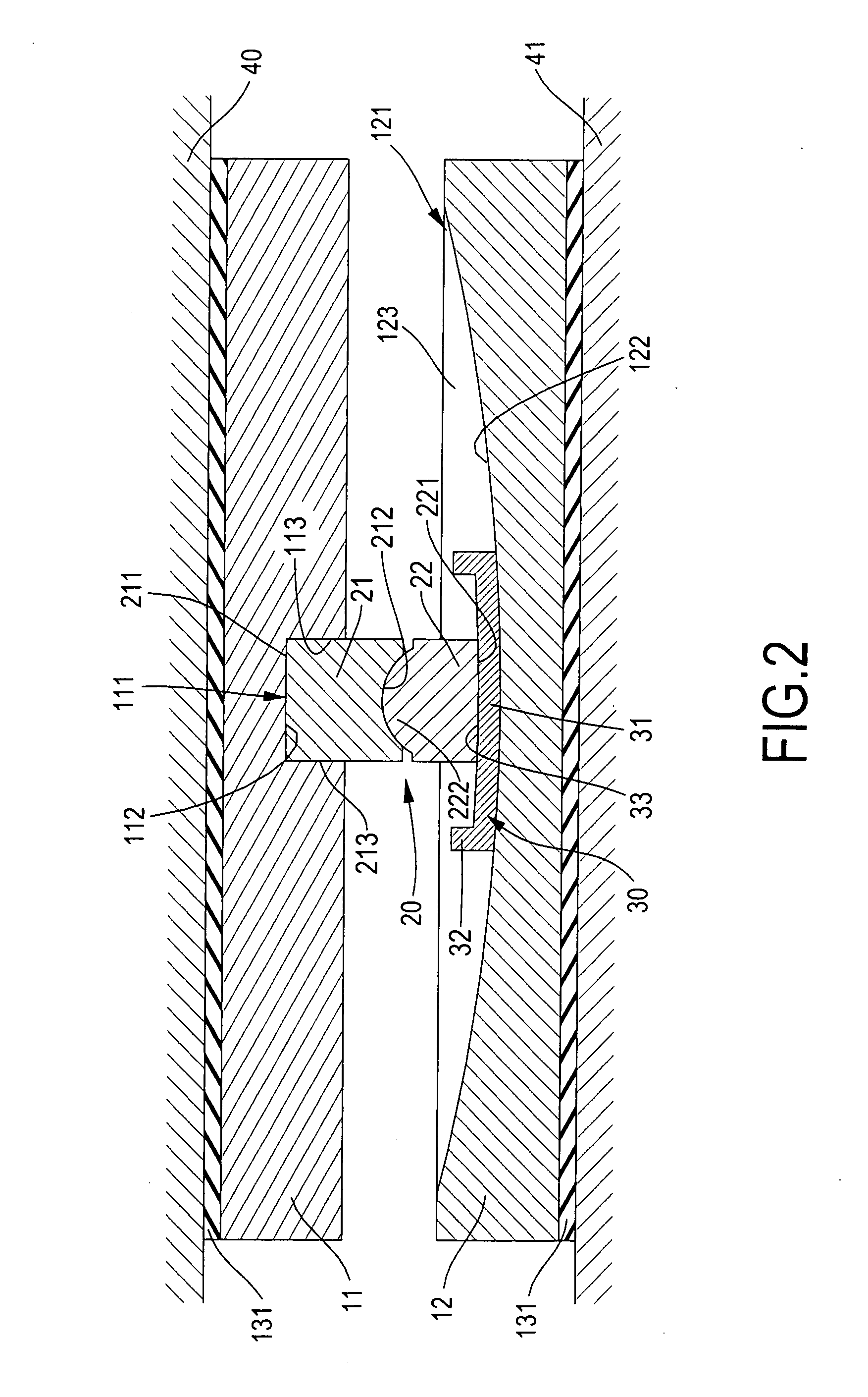
[0026]In a shock suppressor in accordance with the present invention, the first base (11) has an elongated first sliding channel (111) defined in a side facing the second base (12) along a first direction. The first sliding channel (111) has a concave surface (112) facing the second base (12) and two guiding sides (113) facing to and being parallel to each other.

[0027]The second base (12) has an elongated second sliding channel (121) defined in a side facing the first base (11) along a second direction different from but preferably perpendicular to the first direction. The second sliding channel (121) has a concave surface (122) facing the first base (11) and two guiding sides (123) facing to and being parallel to each other.

[0028]The damping device (13) comprises two damping pads (131) attached respectively to the first and second bases (11,12).

[0029]The sliding holder assembly (30) comprises a single sliding holder (31) mounted slidably in the second sliding channel (121) in the s...

second embodiment

[0037]With reference to FIG. 3, in the shock suppressor, the connecting device (20A) may be a rod having two convex ends abutting and matching respectively with the concave surface (112) in the first sliding channel (111) and the concave bottom in the recess (33) of the sliding holder (31).

[0038]With reference to FIG. 4, a third embodiment of the shock suppressor has a structure substantially same as that in the first embodiment except that the universal connector of the connecting device (20B) comprises two recesses (211B,221B) and a supporting member (23B). The recesses (211B,221B) are defined respectively in the facing ends of the first slider (21B) and the second slider (22B). The supporting member (23B) is rotatably mounted in the recesses (211B,221B) in the first and second sliders (21B,22B). In the third embodiment, the recesses (211B,221B) in the first and second sliders (21B,22B) are hemispherical, and the supporting member (23B) is spherical. The damping device (13B) compr...

fourth embodiment

[0039]With reference to FIG. 5, in the shock suppressor, the first base (11A) has two parallel side plates (116A,117A) formed on and extending from the side facing the second base (12A) and a guiding block (115A) mounted between the side plates (116A,117A) to define the first sliding channel (111A) between the side plates (116A,117A) and the guiding block (115A). The guiding block (115A) has a concave surface (112A) facing the second base (12A) and corresponding to and matching with the convex end on the connecting device (20).

[0040]The second base (12A) has two parallel side plates (126A, 127A) formed on and extending from the side facing the first base (11A) and a guiding block (125A) mounted between the side plates (126A,127A) to define the sliding channel (121A) between the side plates (126A,127A) and the guiding block (125A). The guiding block (125A) has a concave surface (122A) facing the first base (11A) and corresponding to and matching with the convex bottom on the sliding ...


PUM


Abstract

A shock suppressor has a first base, a second base, a sliding holder assembly and a connecting device. The first base has an elongated first sliding channel in a first direction. The second base is parallel to the first base and has an elongated second sliding channel in a second direction. The connecting device is slidably mounted between the first and second sliding channels. The sliding holder assembly is mounted between the connecting device and at least one of the bases. The first base is connected with one of the convex ends of the connecting device in a curved contact surface to provide a first sliding mechanism in a first unidirectional sliding direction. The second base is connected with the other convex end of the connecting device to provide a second sliding mechanism in a second unidirectional sliding direction.

Description

BACKGROUND OF THE INVENTION[0001]1. Field of the Invention[0002]The present invention relates to a shock suppressor for a building, a bridge or a motion sensitive equipment, and more particularly to a shock suppressor that can dissipate seismic shock energy in both horizontal and vertical directions efficiently.[0003]2. Description of Related Art[0004]With the decrease of construction area, heights of buildings become higher and higher, so effect of ground motions is very important factors to be considered in the design of a building, a bridge or a skyscraper. Therefore, shock reduction is very important aspect in a construction, and shock suppressors are widely used in a building, a bridge or a skyscraper. Additionally, to improve precision of sophisticated machines, shock suppressors are also applied to the machines.[0005]A conventional shock suppressor is provided to dissipate shock energy and substantially comprises a top base, a bottom base and a slider. The bases are attached ...

Claims


Application Information

Patent Timeline
Patent Type & Authority Applications(United States)
IPC IPC(8): E04B1/98
CPCE04H9/023E04H9/021
Inventor TSAI, CHONG-SHIEN
Owner TSAI CHONG SHIEN
Why Eureka
Try Eureka