Dielectric loaded elliptical helix antenna

a technology of elliptical helical antenna and integrated wire, which is applied in the direction of antenna details, non-resonant long antennas, antennas, etc., can solve the problems of narrow bandwidth, large overall size and cost of patch antenna array, and low-profile antenna fabrication

Active Publication Date: 2012-06-21
CITY UNIVERSITY OF HONG KONG
View PDF2 Cites 4 Cited by
  • Summary
  • Abstract
  • Description
  • Claims
  • Application Information

AI Technical Summary

Benefits of technology

[0006]An object of the invention is to mitigate or obviate to some degree one or more problems associated with known integrated wire helical antennas.

Problems solved by technology

Antennas for RFID readers should be directional, but conventional circularly polarized patch antennas suffer from narrow bandwidth and the directivity of patch antennas is not high enough for them to function as a good RFID base station antenna.
Furthermore, a patch antenna array is one way to achieve high directivity signal radiation, but this comes at the cost of a large overall size and cost of the patch antenna array.
However, the large pitch angle for the traditional axial mode helix antenna prevents the fabrication of a low-profile antenna.
In other words, the physical height of the axial mode helix will be too high to be a good RFID base station antenna.

Method used


Image

  • Dielectric loaded elliptical helix antenna
  • Dielectric loaded elliptical helix antenna
  • Dielectric loaded elliptical helix antenna

Examples


Embodiment Construction

[0032]The following description is of preferred embodiments by way of example only and without limitation to the combination of features necessary for carrying the invention into effect.

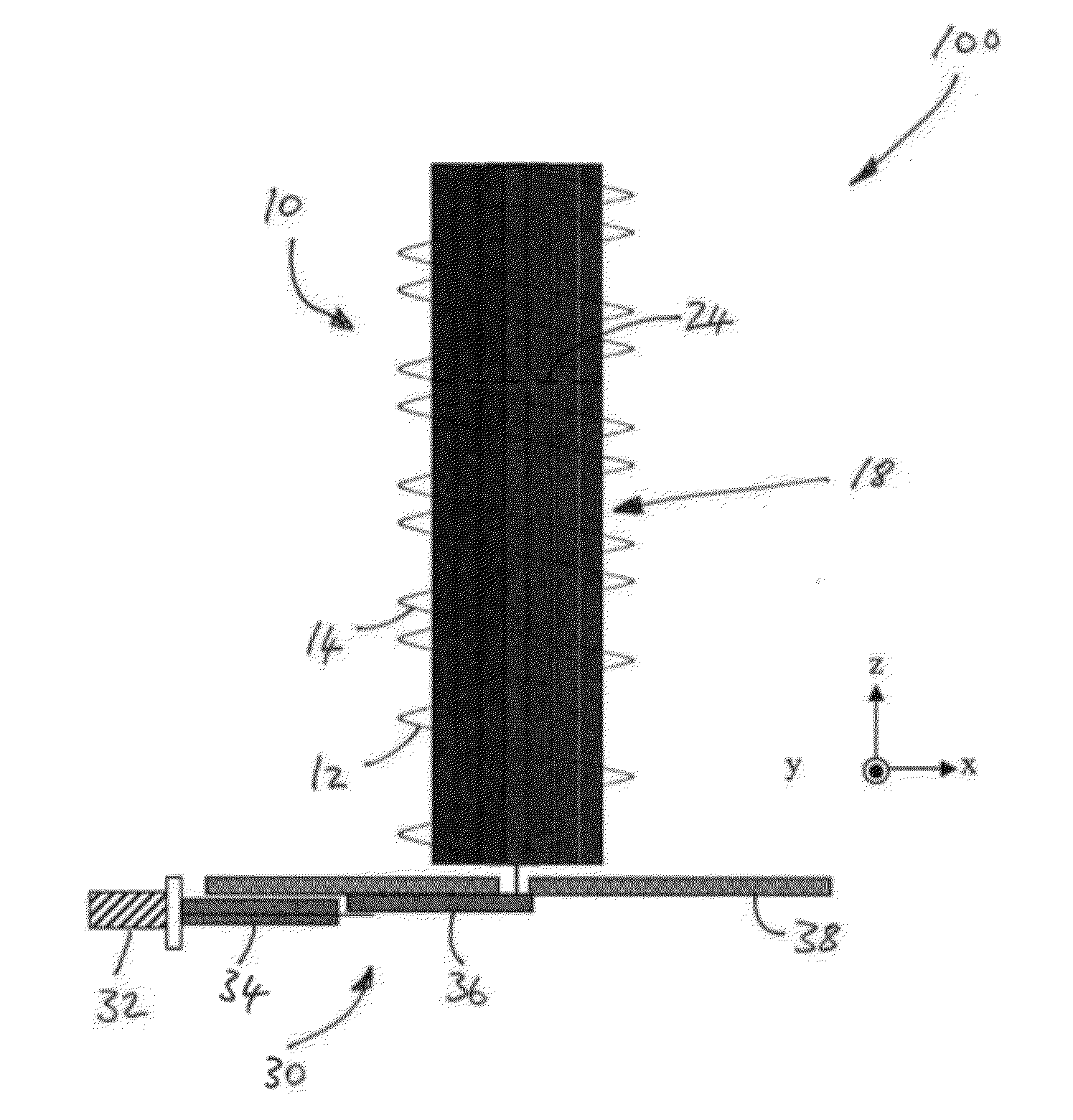
[0033]As will be seen in the following description, in preferred embodiments of the present invention, a relatively narrow beamwidth, wideband with low profile helical antenna 100 which preferably operates in the radio frequency (RF) range of 880 MHz to 940 MHz is described. This antenna 100 is fabricated from a helix 10 of any suitable elongated conducting material (e.g. 6 or more turns which may be modified depending on the desired radiation beamwidth), preferably metal wire such as steel or copper wire, and employs an acrylic plastic as a supporting platform.

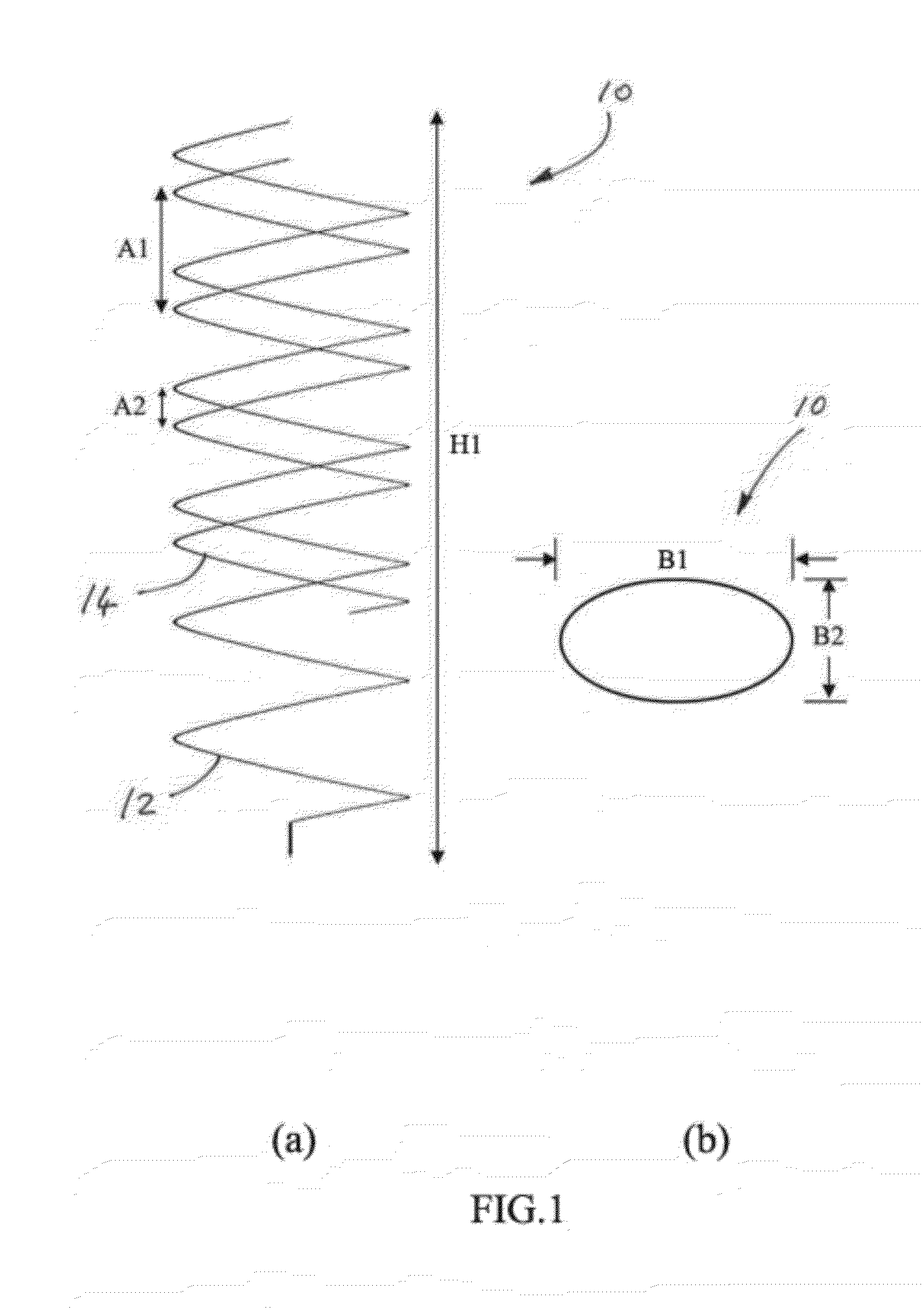
[0034]FIGS. 1(a) and (b) illustrate the geometry of a helix antenna geometry suitable for embodiments of the invention showing (a) a side view of the elliptical helix 10 and (b) a top view of the elliptical helix 10.

[0035]In FIGS. 1(a) and (b)...


PUM


Abstract

An integrated wire elliptical helical antenna with novel cuboids dielectric resonator loading for circularly polarized wave transmission and reception is presented. The antenna is designed to operate in the centre frequency of 915 MHz and it is utilized in RFID systems as a base station antenna. The elliptical structure is formed by steel wire and supporting acrylic plastic. The cuboids dielectric resonator is loaded at the inner surface of the proposed antenna.

Description

FIELD OF THE INVENTION[0001]The present invention relates to an integrated wire elliptical helical antenna for circularly polarized transmission and reception of signals and to an electronic apparatus or system including such an antenna.BACKGROUND OF THE INVENTION[0002]With increasing demands on commercial data transmission applications such as radio frequency identification (RFID) tag applications, attention has been applied to the design of compact integrated and directional antennas with circular polarization and good matching performance. Traditionally, engineers prefer deploying patch antennas in RFID systems because patch antennas have many advantages such as having a low profile, being conformal to planar surfaces, and the ability to integrate the antenna with a printed circuit such as a monolithic microwave integrated circuit (MMIC).[0003]Antennas for RFID readers should be directional, but conventional circularly polarized patch antennas suffer from narrow bandwidth and the...

Claims


Application Information

Patent Timeline
Patent Type & Authority Applications(United States)
IPC IPC(8): H01Q1/38
CPCH01Q1/2216H01Q11/08H01Q7/06
Inventor YUNG, KAI NINGCHAN, PAK WAIWONG, HANGCHE, WENQUAN
Owner CITY UNIVERSITY OF HONG KONG
Why Eureka
Try Eureka