Partial wall-flow filter and diesel exhaust system and method

a wall-flow filter and diesel exhaust technology, applied in the field of wall-flow filters, can solve the problems of large temperature spikes, power loss, and “active” regeneration comes with a fuel economy penalty, and achieve the effect of promoting a significant amount of “active” regeneration

Inactive Publication Date: 2008-05-29
CORNING INC
View PDF12 Cites 40 Cited by
  • Summary
  • Abstract
  • Description
  • Claims
  • Application Information

AI Technical Summary

Benefits of technology

[0005]In view of the inefficiencies of the exhaust systems of the prior art, diesel exhaust after treatment systems operating to a larger extent in a passive regeneration mode may offer a competitive advantage in terms of fuel economy. In one broad aspect, the invention is an exhaust system adapted for venting exhaust gas from an engine, such as a diesel engine, through an exhaust line coupled to the engine. The exhaust system comprises a first particulate filter disposed in the exhaust line and “close-coupled,” i.e., located in close proximity to the engine. and a second particulate filter positioned inline with, and spaced a distance (d) from, the first particulate filter. The spacing between the first and second particulate filters is preferably such that the difference between the inlet temperature of the first filter (T1) and the inlet temperature of the second filter (T2), namely T1-T2, is 20° C. or greater. The first filter is “close-coupled” to the engine so that it operates at a temperature preferably sufficient to promote a significant amount of “passive” regeneration whereas, the downstream second filter operates in a cooler environment and, therefore, relies more on active regeneration for soot removal. The relative extent if passive regeneration undergone in the second filter may be substantially less than in the first (close-coupled) filter. In one implementation, the first particulate filter may have a first percentage of plugged channels and a second percentage of unplugged flow-through channels. According to additional embodiments, the plugged channels may be plugged adjacent to both an inlet end and an outlet end. In a preferred implementation, the second particulate filter is positioned inline with, and spaced a distance (d) of greater than or equal to 12 inches (30.5 cm) from, the first particulate filter. Optionally, the spacing may be such that the first particulate filter may include a first inlet temperature (T1) and the second particulate filter includes a second inlet temperature (T2), wherein a ratio of inlet temperatures (T1 / T2) is greater than or equal to 1.1, or even greater than or equal to 1.15. According to further embodiments of the invention, the first and second particulate filters may be mounted into separate housings. A diesel oxidation catalyst may be included in the system between the filters or the oxidation catalyst function may be included in the first filter.

Problems solved by technology

Increase in pressure drop across the filter generally results in an increase in backpressure against the engine which, if not controlled, may lead to power loss.
On the other hand, “active” regeneration comes with a fuel economy penalty.
Additionally, there is the possibility of large temperature spikes during “active” regeneration which may be detrimental to the filter.

Method used


Image

  • Partial wall-flow filter and diesel exhaust system and method
  • Partial wall-flow filter and diesel exhaust system and method
  • Partial wall-flow filter and diesel exhaust system and method

Examples


Embodiment Construction

[0018]The invention will now be described in detail with reference to a few preferred embodiments, as illustrated in the accompanying drawings. In describing the preferred embodiments, numerous specific details are set forth in order to provide a thorough understanding of the invention. However, it will be apparent to one skilled in the art that the invention may be practiced without some or all of these specific details. In other instances, well-known features and / or process steps have not been described in detail so as not to unnecessarily obscure the invention. In addition, like or identical reference numerals are used to identify common or similar elements.

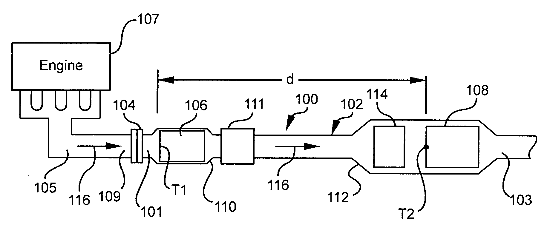
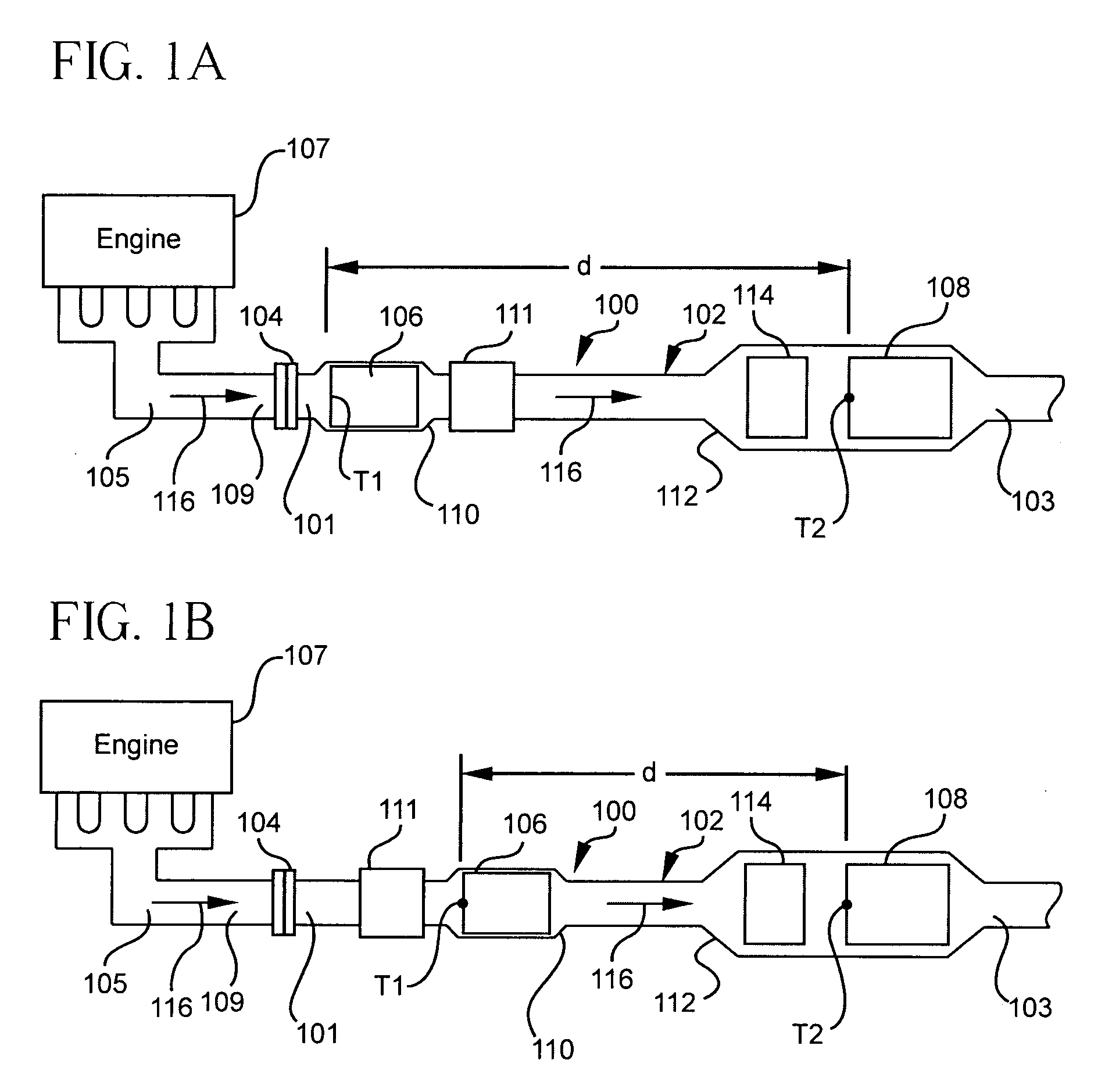
[0019]FIG. 1A depicts an exhaust system 100, such as a diesel exhaust system, for venting exhaust from an exhaust manifold 105 of a diesel engine 107. The exhaust system 100, as shown, includes an exhaust line 102 with inlet end 101 and outlet end 103. The inlet end 101 is coupled to the diesel engine 107 through an exhaust ma...


PUM


Abstract

A exhaust system and method for venting exhaust from an engine, such as a diesel engine, through an exhaust line coupled to the engine includes a first particulate filter disposed in the exhaust line and “close-coupled” with the engine, and a second particulate filter spaced a distance (d) from the first filter. The first particulate filter is “close-coupled” so that it operates in a passive regeneration mode to a greater extent than the second particulate filter. The first particulate filter may be a partial wall-flow filter including some plugged and some open channels. Some of the plugged channels may be plugged adjacent to an inlet end and others may be plugged adjacent to an outlet end. A partial wall-flow filter is also described having some unplugged flow-through channels and some plugged channels wherein some plugged channels are located adjacent to the inlet end and some are located adjacent to the outlet end.

Description

BACKGROUND OF THE INVENTION[0001]The present invention relates generally to wall-flow filters used to filter exhaust gases, and exhaust systems and methods incorporating such filters.[0002]Diesel exhaust systems may include, for example, a diesel particulate filters (DPFs) for removing particulates, such as soot from diesel exhaust. Where multiple DPFs are used to remove particulates, these DPFs are typically arranged in close proximity to each other and housed within a common enclosure, such as taught in US Pat. App. No. 2004 / 0161373. The most widely used DPFs are wall-flow filter. The conventional wall-flow filter consists of a ceramic honeycomb substrate having longitudinal, parallel cell channels formed by a plurality of intersecting porous walls. The ends of the cell channels are typically plugged with a ceramic plugging cement to form a checkered pattern of plugs at the end faces of the honeycomb substrate. The cell channels of the filter typically have some ends plugged at an...

Claims


Application Information

Patent Timeline
Patent Type & Authority Applications(United States)
IPC IPC(8): F01N3/022F01N3/023
CPCF01N3/021F01N3/0222F01N3/0231F01N3/031F01N13/009F01N2330/06F01N2340/04F01N13/0093F01N3/035
Inventor BEALL, DOUGLAS MUNROEHEIBEL, ACHIM KARL-ERICHTANDON, PUSHKAR
Owner CORNING INC
Why Eureka
Try Eureka