Suction apparatus and connectors

a technology of suction apparatus and connectors, applied in the direction of respirator, trachea tube, etc., can solve the problem of increasing the risk of infection

Inactive Publication Date: 2008-05-29
SMITHS GRP PLC
View PDF27 Cites 40 Cited by
  • Summary
  • Abstract
  • Description
  • Claims
  • Application Information

AI Technical Summary

Problems solved by technology

It is, however, undesirable to have to break the suction circuit each time that lavage needs to be administered since this takes time, can result in the unhygenic release of secretions from the suction tube and can increase the risk of infection.

Method used


Image

  • Suction apparatus and connectors
  • Suction apparatus and connectors
  • Suction apparatus and connectors

Examples


Embodiment Construction

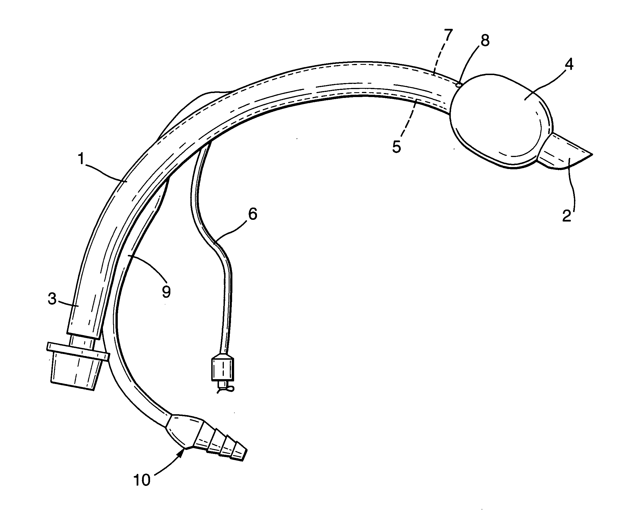
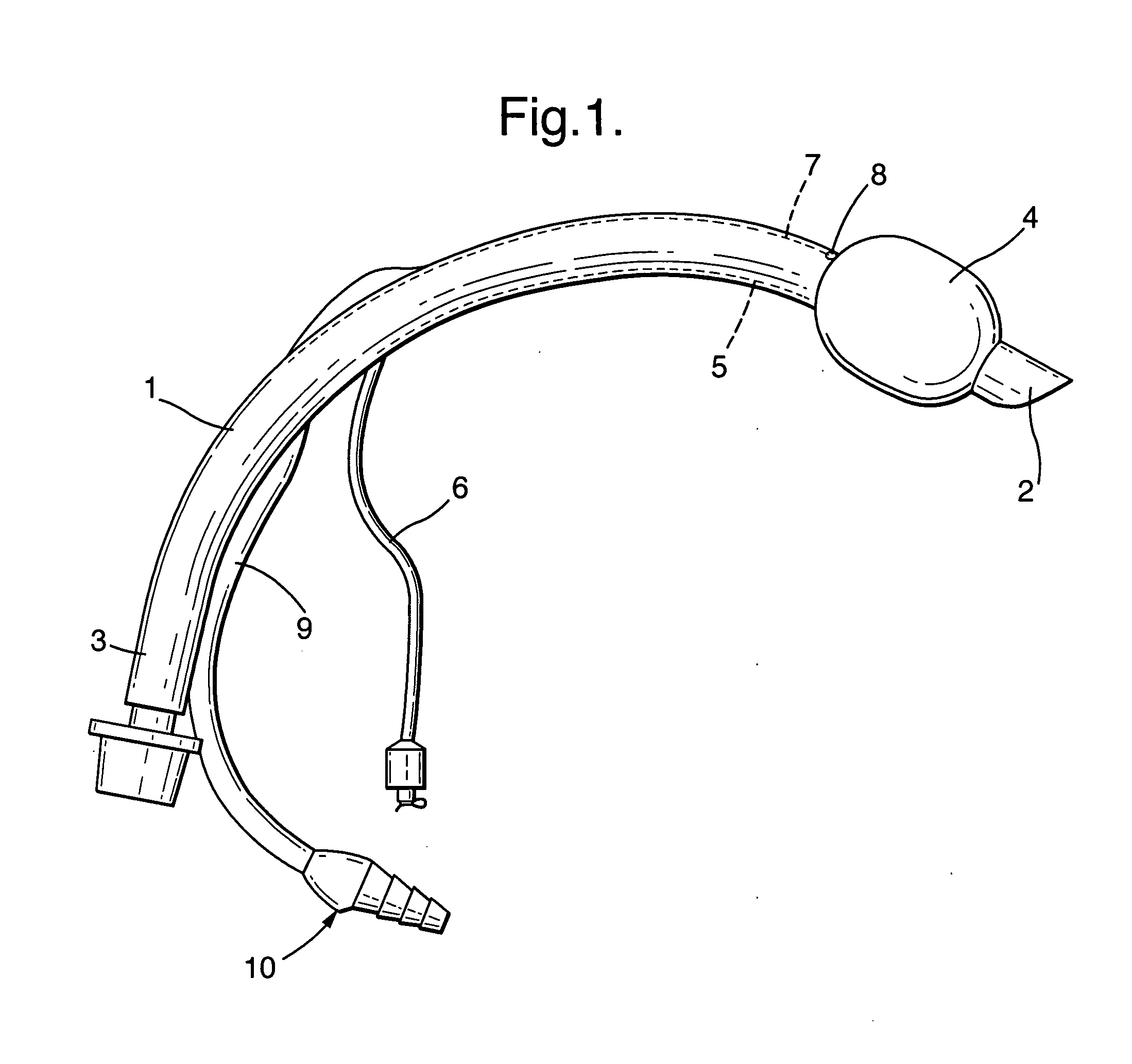
[0014]With reference first to FIGS. 1 to 4 the endotracheal tube includes a curved shaft 1 with an angled patient end 2 and a machine end 3 at the opposite end of the shaft. An inflatable sealing cuff 4 is attached to the shaft 1 close to its patient end 2 and this is inflated or deflated via an inflation lumen 5 extruded within the wall of the shaft along the inside curve of the shaft. A small-bore inflation line 6 is attached to an opening in the inflation lumen 5 about midway along the tube. The tube also has a suction / lavage lumen 7 extruded within the wall of the shaft 1 and extending along the outside curve of the shaft. The suction / lavage lumen 7 opens through an aperture 8 formed in the outside of the shaft 1 close to the upper, machine end of the cuff 4. The suction / lavage lumen 7 is connected with one end of a small-bore suction / lavage line 9 about midway along the length of the tube. The suction / lavage line 9 is a flexible tube and is terminated at its other, free end by ...


PUM


Abstract

A tracheal tube has a sealing cuff towards its patient end and a suction aperture just above the cuff. The suction aperture connects via a lumen with a suction line terminated by a connector. One end of the connector is tapered and has a port for connection to a suction source. The connector also has a side port in which the nose of a syringe can be inserted to inject a lavage fluid out of the suction aperture to help loosen secretions. When not in use, the side port is closed by a valve or by a closure cap with formations for sealing the two ports.

Description

BACKGROUND OF THE INVENTION [0001]This invention relates to suction apparatus and connectors.[0002]There are various medical procedures where suctioning is needed, such as to remove accumulations of secretions, irrigation fluid, blood or other body fluids. One example is cuffed tracheal tubes where it is desirable to remove secretions that collect in the trachea above the cuff. With such tracheal tubes, a suction lumen may be extruded within the wall of the tube and open via an aperture towards its patient end just above the cuff. The suction lumen is connected, towards its other end, to a small-bore suction line terminated with a coupling to which a source of suction can be connected. An example of a tracheal tube having such a suction lumen is described in U.S. Pat. No. 5,201,310. In some cases it is necessary to introduce a lavage solution, such as saline, via the suction lumen to aid in the removal of the secretions. This is presently done by disconnecting the machine end coupli...

Claims


Application Information

Patent Timeline
Patent Type & Authority Applications(United States)
IPC IPC(8): A61M16/04
CPCA61M16/0479A61M16/0463A61M16/0486
Inventor FIELD, STEPHEN JAMES
Owner SMITHS GRP PLC
Why Eureka
Try Eureka