Portable communication display device

a display device and portability technology, applied in the direction of mountings, polarising elements, instruments, etc., can solve the problems of low resolution of existing displays, large size and weight of head mounted displays, etc., and achieve the effect of preventing injury from falling objects

Inactive Publication Date: 2008-05-29
KOPIN CORPORATION
View PDF72 Cites 204 Cited by
  • Summary
  • Abstract
  • Description
  • Claims
  • Application Information

AI Technical Summary

Benefits of technology

[0009]System electronics and manually adjustable controls can be positioned within the housing or the rotating arms, or on bands extending above or behind the head of the user. Positioning of the electronics and controls within the arms or bands permits a more desirable distribution of weight evenly about the sides or top of the user's head.
[0014]A preferred embodiment provides protective headgear such as safety glasses, hardhats and helmets for a number of commercial and industrial applications. For embodiments including hardhats and helmets, the system includes a rigid protective headpieces covering the head of the user to prevent injury from falling objects. The protective headgear is dimensioned to work in combination with an electronic display mounted on a frame which can be secured to the user's head using several alternative devices. The frame can be mounted to the rigid headpiece by clipping or otherwise securing the frame to the headpiece visor or a receptacle on that portion of the headpiece adjacent one ear of the user. Alternatively, the frame can be mounted on or within the helmet. The frame can include a first track to permit the user to move the display from a retracted position to a viewing position within the field of view of the user. This system can be a monocular system or a binocular system using two displays. The monocular system can be placed on a second horizontal track so that the user can center the display in front of either eye.

Problems solved by technology

Head mounted displays are generally limited by their resolution and by their size and weight.
Existing displays have relatively low resolution, and because of the size and weight of available systems, these displays are often positioned at the relatively large distance from the eye.

Method used


Image

  • Portable communication display device
  • Portable communication display device
  • Portable communication display device

Examples


Embodiment Construction

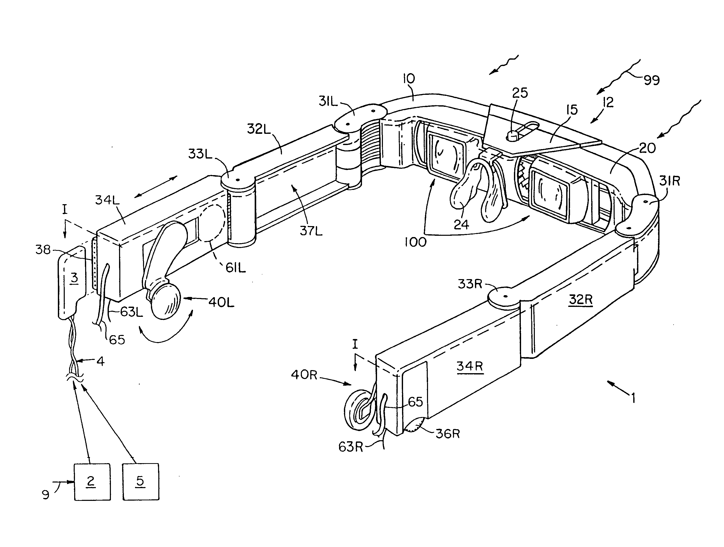
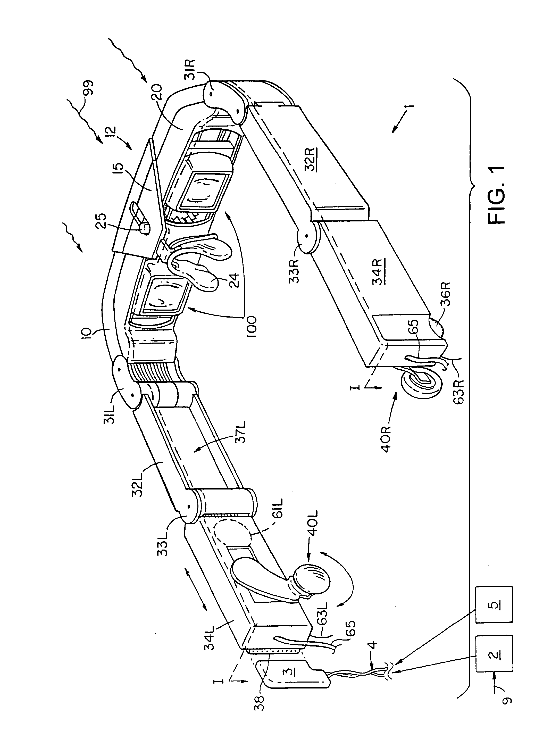
[0092]FIG. 1 is a rear perspective view of a preferred embodiment of a head mounted display 1. The head mounted display 1 is constructed of plastic or some other light-weight housing material and is adapted to be worn by a user to view video images via an optical assembly 100. The head mounted display exploits electronic digital imaging to form video images on a pair of light valve display panels, one of which is viewed through the user's left eye and the other of which is viewed through the user's right eye. Related discussions of head mounted display devices are provided in U.S. patent application Ser. No. 07 / 971,352, filed Nov. 4, 1992 and International Patent Publication WO 93 / 18428, filed Mar. 12, 1992, the teachings of which are both incorporated herein by reference.

[0093]The images are provided by a remote video source 2, which can be a camera, a computer, a receiver, a video cassette player, or any device that can transmit a video signal. The video source 2 may generate of v...


PUM


Abstract

A head-mounted display system displays information via a matrix display element mounted within a housing that is positioned relative to at least eye of a user. The display is connected to a video or information source such that the user can view information or images shown on the display. The display can be mounted to a frame so that the user can move the display in and out of the user's field of view without adjusting the supporting harness that holds the display on the user's head.

Description

RELATED APPLICATIONS[0001]This application is a Continuation application of U.S. Ser. No. 08 / 857,273 filed May 16, 1997 which is a File Wrapper Continuation of Ser. No. 08 / 717,536 filed Sep. 23, 1996, which is a File Wrapper Continuation of Ser. No. 08 / 327,113 filed Oct. 21, 1994, which is a continuation in part of Ser. No. 08 / 287,970 filed Aug. 9, 1994 which is a Continuation-in-Part of U.S. Ser. No. 08 / 220,042, filed on Mar. 30, 1994 which is a Continuation-in-Part of U.S. Ser. No. 08 / 141,133, filed on Oct. 22, 1993; the teachings of which are being incorporated herein by reference in their entirety.BACKGROUND OF THE INVENTION[0002]Head mounted display systems have been developed for a number of different applications including use by aircraft pilots and for simulation such as virtual imaging. Head mounted displays are generally limited by their resolution and by their size and weight.[0003]Existing displays have relatively low resolution, and because of the size and weight of ava...

Claims


Application Information

Patent Timeline
Patent Type & Authority Applications(United States)
IPC IPC(8): G09G5/00G02B5/18G02B5/30G02B7/12G02B27/00G02B27/01
CPCG02B5/18G02B2027/0187G02B7/12G02B27/017G02B27/0172G02B27/0176G02B2027/011G02B2027/0132G02B2027/0138G02B2027/0143G02B2027/0154G02B2027/0156G02B2027/0158G02B2027/0159G02B2027/0178G02B5/30
Inventor RONZANI, PETER A.JACOBSEN, JEFFREYGALE, RONALDPOMBO, STEPHEN
Owner KOPIN CORPORATION
Why Eureka
Try Eureka