Scalable reconfigurable router

a router and reconfigurable technology, applied in the field of routers, can solve the problems of time-consuming effort, inability to add more i/o cards “on demand, and the capacity of most conventional router sfs (e.g. bus or crossbar) cannot be easily expanded on demand, so as to achieve rapid bi-directional reconfigurability/interchangeability, reduce the cost of performing, and save capital cost

Active Publication Date: 2008-05-29
AT & T INTPROP II LP
View PDF22 Cites 61 Cited by
  • Summary
  • Abstract
  • Description
  • Claims
  • Application Information

AI Technical Summary

Benefits of technology

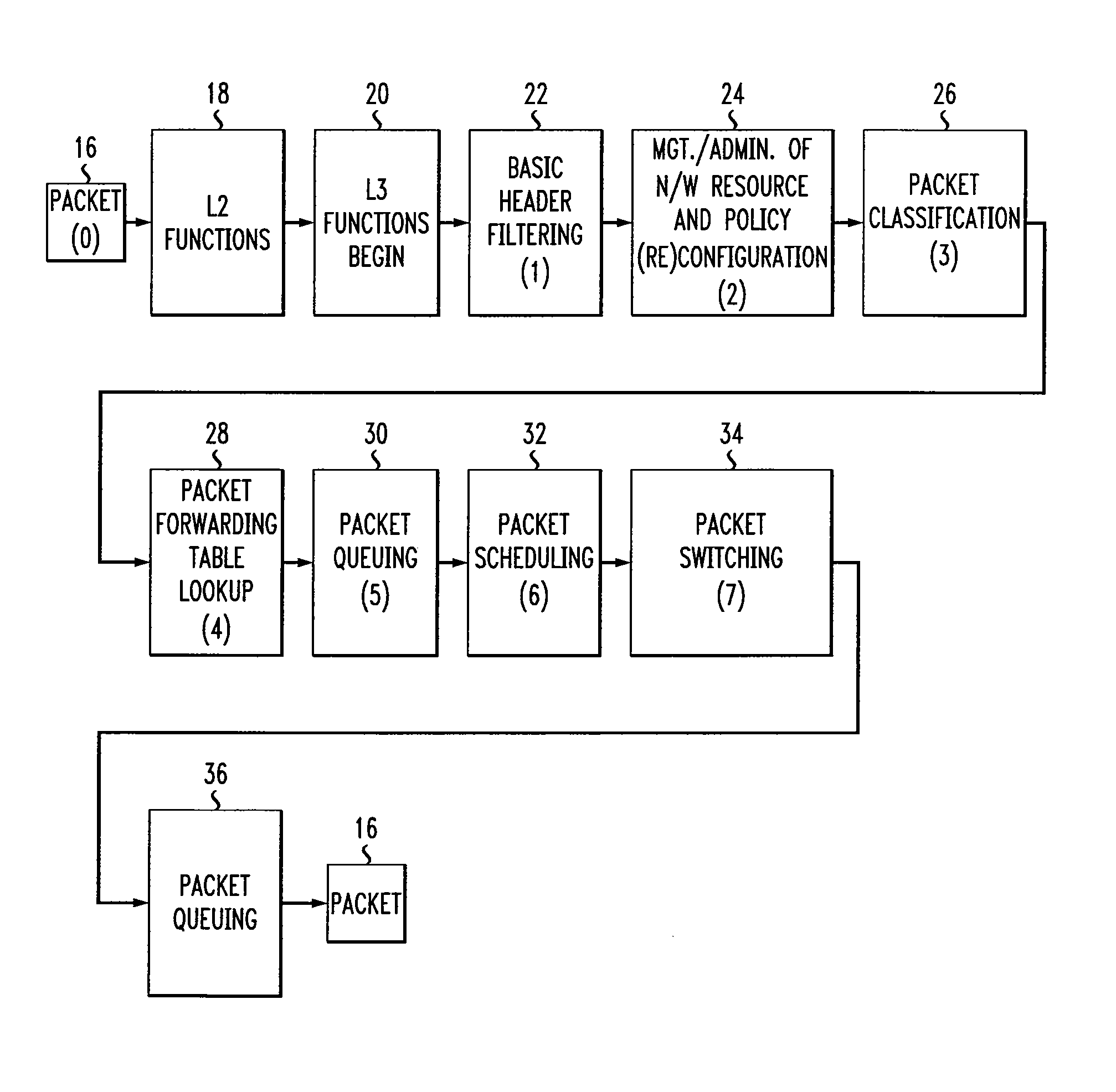
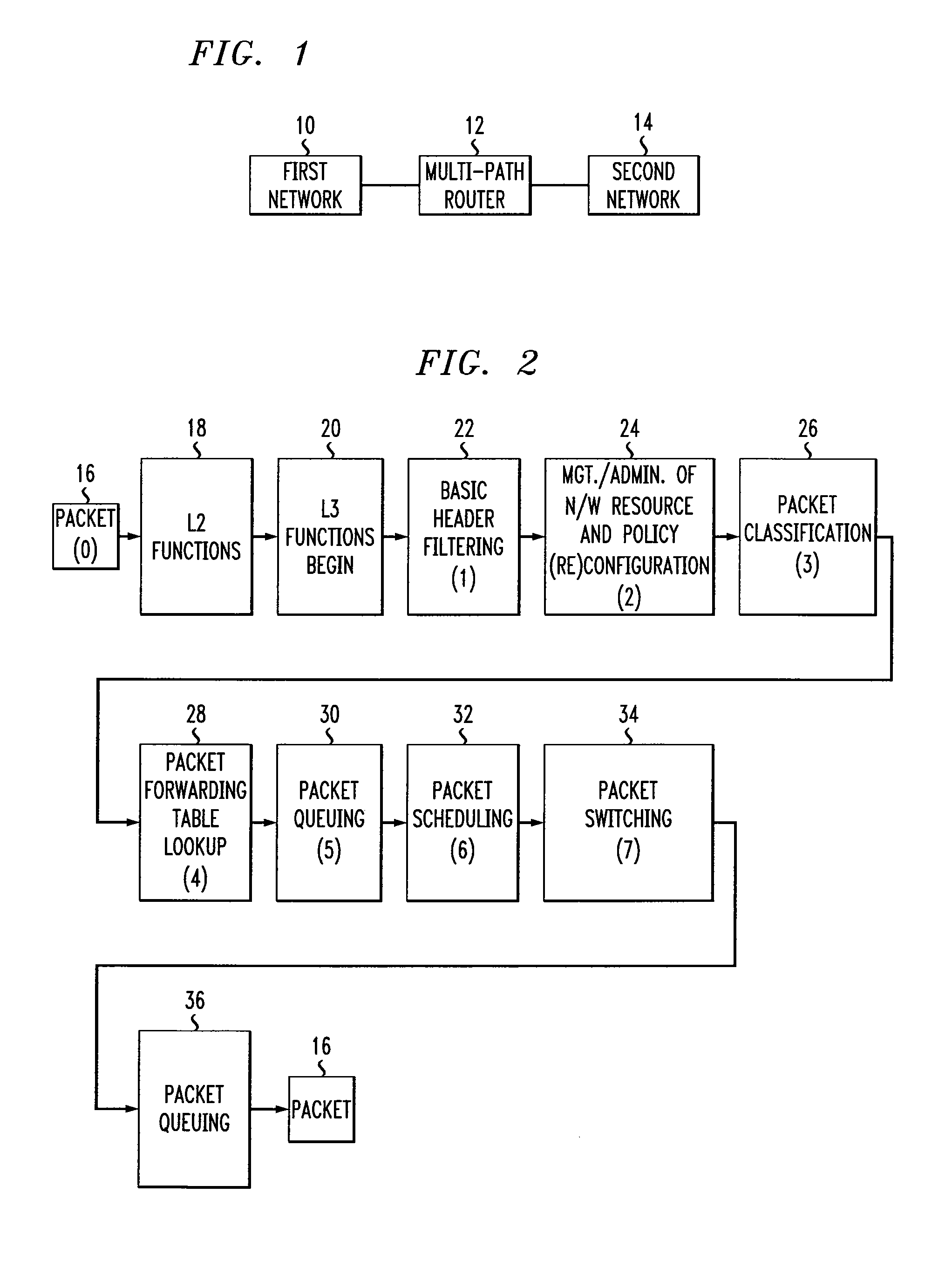
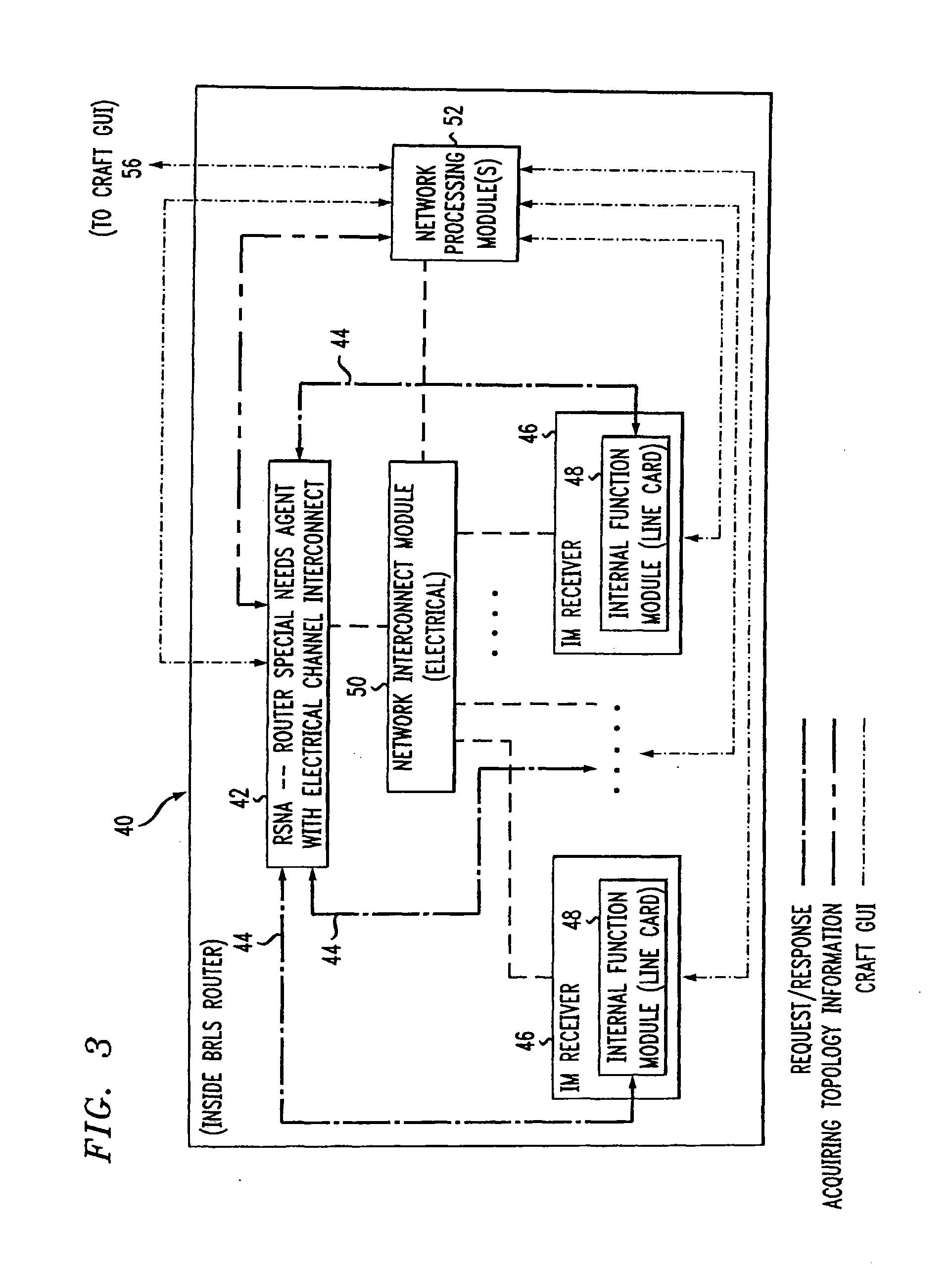
[0021]With this particular arrangement, a multi-path router capable of rapid bi-directional hardware reconfigurability is provided. The RSNA component primarily performs the “edge” layer / (Quality of Service) QoS control plane functions and administers management and control for headers of packets with special (e.g., priority / network resource) requirements. In addition to QoS control plane, the RSNA also performs some data plane functions in the processing of the packet headers. By utilizing the RSNA as part of an overall router hardware architecture, the router is quickly “bi-directionally” interchangeable either downward as “edge router”, or upward as a “hub or “backbone router,” and provides an immediate hardware resource suitable for use in all layers of a network hierarchy such as an internet service provider (ISP) network hierarchy, for example. The multi-path router thus allows speedy and yet manpower and cost-efficient network hardware expansions / upgrades and network emergency fixes / responses to be performed which is not possible with conventional router hardware architectures.
[0049]In still another embodiment, an architecture utilizes a hybrid reprogrammable chip technology with one being electronic FPGAs or ASICs and the other optoelectronic FPGAs. The architecture also uses a sensor technology to sense incoming traffic speed and based on the sensor result, to route traffic accordingly either via the “almost all-optical” or the “electrical / optical” hardware technology path through the router. The only non-optical part in the “almost-all-optical” processing path is the optoelectronic devices that implement the router's data plane functions within the IMs. This architecture provides all of the benefits of the BRLS and OSR architectures as explained above, as well as the benefit of an “almost all-optical” incoming-traffic-speed-independent hardware path for packet processing through the router.

Problems solved by technology

The new routers also often need to be lab-tested to ensure interoperability with existing hardware and software, an often time-consuming effort before field deployment can be made possible.
However, it is not possible to add more I / O cards “on demand” without a new switch fabric (SF) replacement if the capacity for target expansion were not already built into the router SF at its first implementation.
This is because capacity of most conventional router SFs (e.g. bus or crossbar) cannot be easily expanded on demand.
Moreover, the functionalities of “edge”, “hub” and “backbone” routers cannot be interchanged without also undertaking the time-consuming task of altering internal router hardware architectures required to adapt to the functionality of each router at the “target” network layer.
Consequently, other routers in the network are typically not available as hardware resources to rapidly address upgrade or expansion needs of the different layers.
In particular, it may be required to disable or dismantle physical wires that lead to a policy database / lookup table that is no longer useful in a “backbone” environment (e.g a policy database / lookup table such as packet prioritization based on rules).
Also, if the data path were originally pipelined, the pipeline would need redesign since some pipeline stages must be skipped (or taken out) due to the disabling of the above-mentioned hardware components.
Furthermore, such a pipeline modification may impact and thereby induce a change in the router's clock speed.
Furthermore, each of the above steps is labor-intensive and thus costly and time-consuming.
Hence, upgrade of backbone routers using edge routers is rarely if ever done due to the labor and expense of hardware architectural alteration / re-work necessary stemming from the completely different internal hardware designs for “edge” and “hub / backbone” routers in most vendor products.
Similarly, it is also labor-intensive to adapt a “backbone” or “hub” router today for use as an “edge” router as it would entail the reversal of a number of the tasks listed above.
Also, depending upon the desired target router hardware architectural implementation, the above-mentioned reconfiguration may also involve installing added databases and rewiring to accommodate added physical wires leading to the added databases / memories on a computer board, and if the packet-processing data path was pipelined, the pipeline must be redesigned to accommodate additional stages of database fetching / reading, making the pipeline longer and thus more complex, which could result in degradation of the overall performance of a router.
Another problem which occurs is that a capacity / speed conversion or upgrade of an ISP network having multiple layers of network hierarchy often involves putting together different vendor equipment for the different network layers, as one vendor may not supply routers with different functionalities required for use in different layers of the network.
In such situations, lengthy and expensive network interoperability testing and field (confidence) testing must be conducted for the different equipment from different vendors in the different network layers.
This results in a relatively long lead-time being required in the hardware expansion / upgrade process for all network layers.
Hence, since router hardware expansion / upgrades must often be done network-wide for all network layers to ensure interoperability after the expansion / upgrade, the problem of costly and manpower intensive router hardware upgrades is exasperated with an increase in the numbers of network layers.
Another problem is that since IP QoS control is distributed in each individual router in conventional systems, only hop-by-hop non-optimal, instead of global, view of QoS control is possible.
With QoS control in its distributed form, conventional router hardware architectures cannot scale to include whole-path data storage capacity needed for network whole-path QoS provisioning within the router itself due to router size and / or central office space constraints, among other inefficiencies.
The reason being that to provision conventional routers with global knowledge for network whole-path-related QoS control would mean enormous expense since it would be necessary to equip each router with numerous built-in databases that yield such network-wide information.
Such provisioning is difficult to achieve within the limited space of a router chassis and with equipment footprint size restriction inside the limited space of a central office for routers.
Moreover, frequent and time-consuming synchronization of states amongst routers (often by message exchange in the form of a network protocol) is needed to ensure network-wide data / state coherence.
With the inability to scale efficiently to include whole-path data storage capacity needed for network-wide QoS provisioning, an individual router has no global view of the bandwidth resource for arbitrary routes in the network.
Consequently, it is highly inefficient for a router to provision value-added overall network-wide whole-path-related services such as IP-based VPN which involve routes elsewhere in the network the bandwidth resource status of which is not known to the router unless the router spends the time to “ask” for it via message exchange in the form of specific protocols.
In view of the above, it is clear that conventional router hardware architectures are not designed for cost- and manpower-efficient network hardware expansions or upgrades.
This approach results in the expenditure of large amounts of capital and manpower resources, as well as long hours of “costly” downtime for all parties involved (e.g. ISPs and end users).
The conventional processes for performing a network hardware expansion or upgrade are cost-inefficient and manpower intensive.
Consequently, many companies (e.g. AT&T, Corp.) spend a tremendous amount of energy and resources in the process of network hardware expansions / upgrades.

Method used


Image

  • Scalable reconfigurable router
  • Scalable reconfigurable router
  • Scalable reconfigurable router

Examples


Embodiment Construction

[0062]Before describing the present invention, it should be understood that reference is sometimes made herein to operation of the present invention in connection with internet protocol (IP) networks. Such reference is intended only for clarity and clearness in explanation and description and should not be construed as limiting. It should be understood by those of ordinary skill in the art, that the concepts, apparatus and techniques described herein find application in a wide variety of networks including but not limited to IP networks. Reference is also sometimes made herein to forwarding a packet header to a particular location within a router or to a router special needs agent (RSNA) or to a certain physical or logical path. It should also be understood that in some applications it may be desirable or even necessary to forward the entire packet rather than the packet header alone. Similarly, when reference is made to forwarding or processing a payload, it should be understood th...


PUM


Abstract

A multi-path router includes an interface module (IM) having a time-sensitive logical processing path and a non-time-sensitive logical processing path and a special needs logical processing path and a filter for receiving a packet header and determining the needs of the packet header and for selecting one of: the time-sensitive logical processing path, the non-time sensitive logical processing path and the special needs logical processing path in response to the needs of the packet header. The multi-path router further includes a router special needs agent (RSNA), adapted to receive a packet header having special needs services. The multi-path router can be used in a network which includes first and second networks coupled to the multi-path router and wherein the RSNA receives information from the special needs logical processing path and provides information to the IM on a return path.

Description

RELATED APPLICATIONS[0001]This application is a continuation of co-pending U.S. patent application Ser. No. 10 / 298,308 filed Nov. 18, 2002 entitled SCALABLE, RECONFIGURABLE ROUTERS, which has been allowed. The aforementioned related patent application is herein incorporated by reference.GOVERNMENT RIGHTS[0002]Not Applicable.FIELD OF THE INVENTION[0003]This invention relates generally to routers and more particularly to a scalable and bi-directionally reconfigurable router architecture.BACKGROUND OF THE INVENTION[0004]As is known in the art, “a computer network” or more simply “a network” is a connection of computer systems and peripheral devices that exchange data (or more generally information) as necessary to perform the specific function of the network. To exchange information, networks operate in accordance with a set of semantic and syntactic rules referred to as a protocol. One particular type of protocol is the Transmission Control Protocol / Internet Protocol (TCP / IP). When a ...

Claims


Application Information

Patent Timeline
Patent Type & Authority Applications(United States)
IPC IPC(8): H04L12/56
CPCH04L45/60H04L49/201H04L49/3072H04L49/3009H04L49/205
Inventor TSE-AU, ELIZABETH SUET H.
Owner AT & T INTPROP II LP
Why Eureka
Try Eureka