Method of controlling an irrigation/aspiration system

a technology of irrigation/aspiration system and control method, which is applied in the direction of eye surgery, suction pump, other medical devices, etc., can solve the problems of slow response time, vacuum controlled system is difficult to operate in flow control mode, and lack of occlusion detection

Active Publication Date: 2008-05-29
ALCON INC
View PDF102 Cites 180 Cited by
  • Summary
  • Abstract
  • Description
  • Claims
  • Application Information

AI Technical Summary

Benefits of technology

[0012]A further objective of the present invention to provide an aspiration control system and method that can be operated either as a vacuum priority system or a flow rate priority system.

Problems solved by technology

Disadvantages of such systems are the lack of flow information resulting in high flows during phacoemulsification / fragmentation coupled with a lack of occlusion detection.
Vacuum controlled systems are difficult to operate in a flow controlled mode because of the problem of non-invasively measuring flow in real time.
Disadvantages of such systems are relatively slow response times, undesired occlusion break responses when large compliance components are used and vacuum can not be linearly decreased during tip occlusion.
Flow controlled systems are difficult to operate in a vacuum controlled mode because time delays in measuring vacuum can cause instability in the control loop, reducing dynamic performance.
The peristaltic pump does not provide aspiration vacuum to the surgical site.

Method used


Image

  • Method of controlling an irrigation/aspiration system
  • Method of controlling an irrigation/aspiration system

Examples


Embodiment Construction

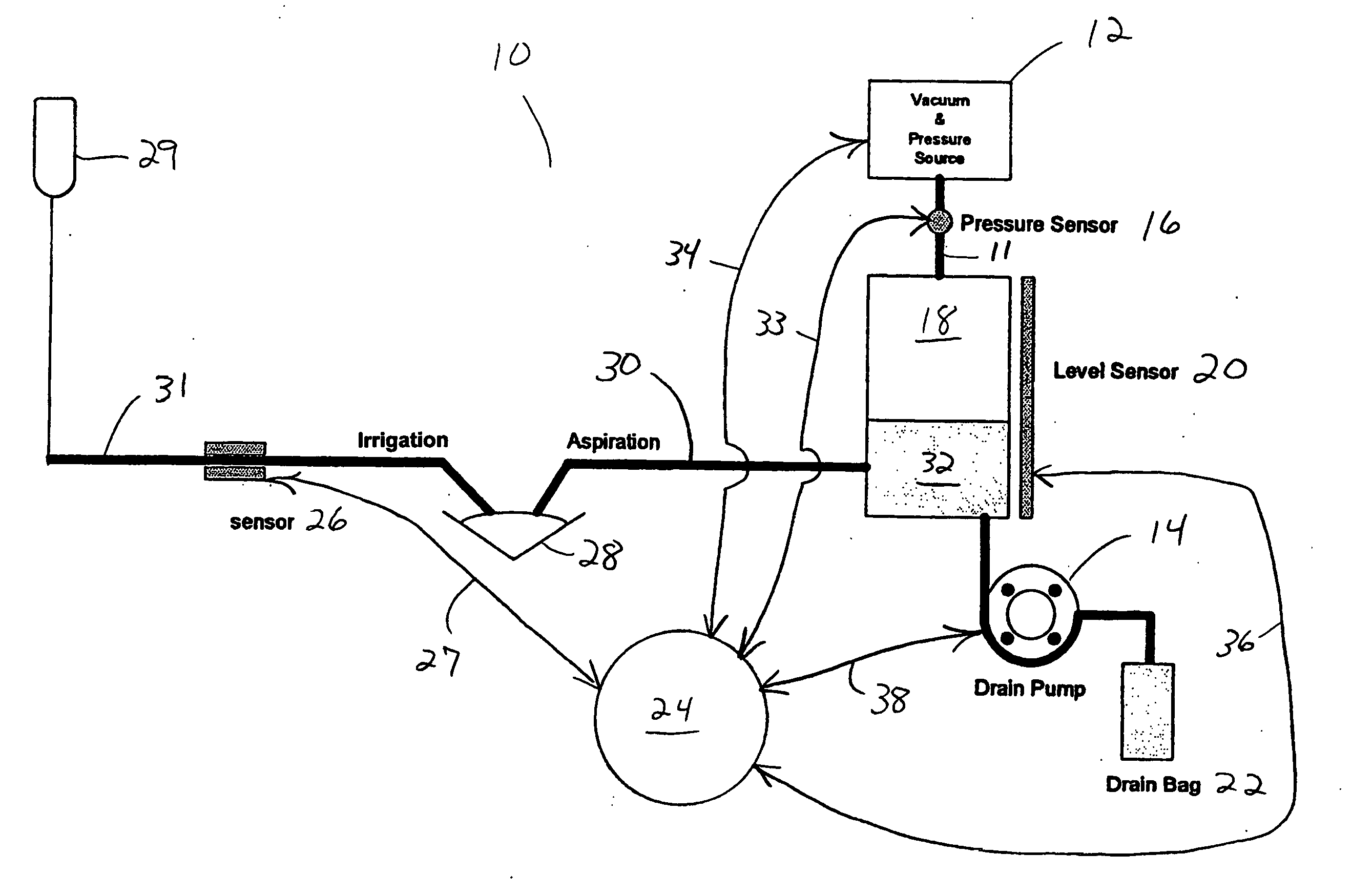
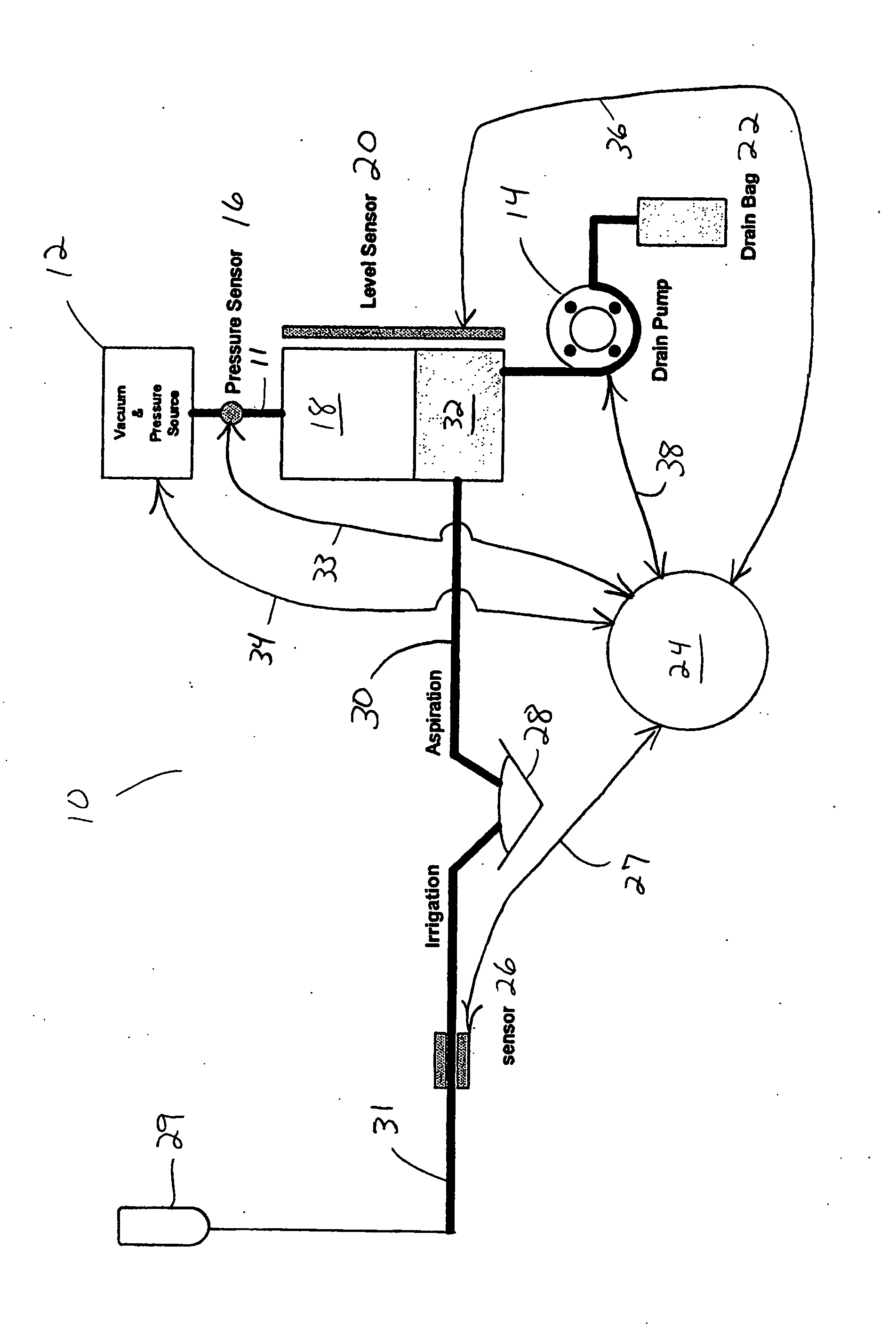
[0015]As best seen in the FIGURE, system 10 of the present invention generally contains vacuum pump 12, flow pump 14, pressure transducer 16, small collection chamber 18, fluid level sensor 20, drain bag 22, control circuitry 24 and sensor 26, such as a flow or pressure sensors. Vacuum pump 12 may be any suitable pump, such as a diaphragm pump, a vane pump, a scroll pump or a peristaltic pump, but a venturi pump is preferred. Pressure transducer 16 may be any suitable device for directly or indirectly measuring pressure or vacuum, such as a vacuum transducer or an absolute pressure transducer. One suitable system for controlling vacuum pump 12 is disclosed in U.S. Pat. No. 5,674,194, the entire contents of which being incorporated herein by reference. Flow pump 14 may be any suitable pump, such as a venturi pump, a diaphragm pump, a vane pump or a scroll pump, but a peristaltic pump is preferred. Fluid level sensor 20 may be any suitable device for measuring the fluid level in small...


PUM


Abstract

A dual pump aspiration system having both a vacuum level control loop and a flow rate control loop. The system can be operated either as a vacuum priority system or a flow rate priority system.

Description

[0001]This invention relates to surgical control consoles and more particularly to irrigation / aspiration systems used in surgical control consoles.BACKGROUND OF THE INVENTION [0002]During small incision surgery, and particularly during ophthalmic surgery, small probes are inserted into the operative site to cut, remove or otherwise manipulate tissue. During these surgical procedures, the surgical site typically is flushed with an irrigating solution and the irrigating solution and tissue is aspirated from the surgical site. The types of aspiration system used, prior to the present invention, where generally characterized as either flow controlled or vacuum controlled, depending upon the type of pump used in the system, and each type of system has certain advantages.[0003]Vacuum controlled aspiration systems are operated by setting a desired vacuum level, which the system seeks to maintain. Flow rate information is not available directly. Vacuum controlled aspiration systems typicall...

Claims


Application Information

Patent Timeline
Patent Type & Authority Applications(United States)
IPC IPC(8): A61F9/007A61M1/00
CPCA61F9/007A61M1/0074A61M1/0058A61M1/0031A61M1/802A61M1/74A61M1/77
Inventor GAO, SHAWN X.
Owner ALCON INC
Why Eureka
Try Eureka