Application of vacuum as a method and mechanism for controlling eye chamber stability

a technology of eye chamber and vacuum, applied in the field of surgical methods, can solve the problems of greater vacuum, negative pressure in the aspiration line, increased vacuum, etc., and achieve the effect of increasing the level of aspiration for

Active Publication Date: 2006-10-05
JOHNSON & JOHNSON SURGICAL VISION INC
View PDF16 Cites 36 Cited by
  • Summary
  • Abstract
  • Description
  • Claims
  • Application Information

AI Technical Summary

Benefits of technology

[0018] More particularly, the vacuum may be controlled by lowering a maximum level of vacuum allowed during an occluded state of a surgical procedure. In addition, a method in accordance with the present invention may include further determining a vacuum drop from the sensed vacuum level

Problems solved by technology

This blockage can result in increased vacuum (i.e. increasingly negative pressure) in the aspiration line and the longer the occlusion is in place the greater the vacuum.
Such post-occlusion surge may lead to eye trauma.
Current precautions against post-occlusion surge cause cataract surgery to be lengthier and more difficult for an attending surgeon.
This technique, however, requires a surgeon to discontinue applying ultrasonic power temporarily until

Method used


Image

  • Application of vacuum as a method and mechanism for controlling eye chamber stability
  • Application of vacuum as a method and mechanism for controlling eye chamber stability
  • Application of vacuum as a method and mechanism for controlling eye chamber stability

Examples


Embodiment Construction

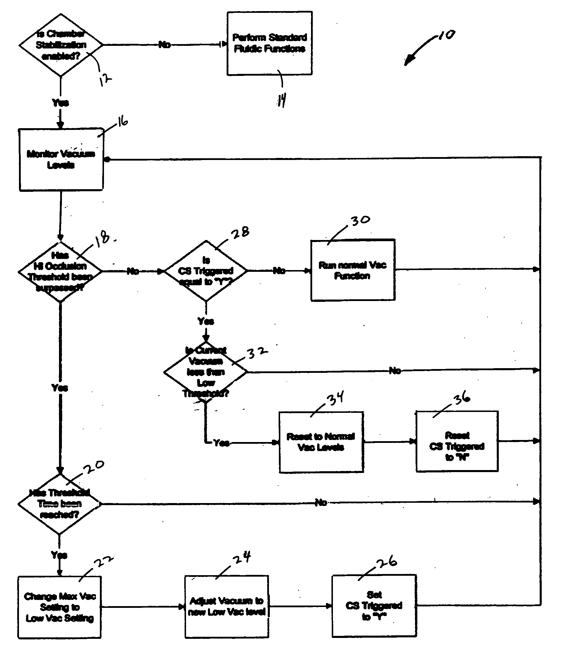
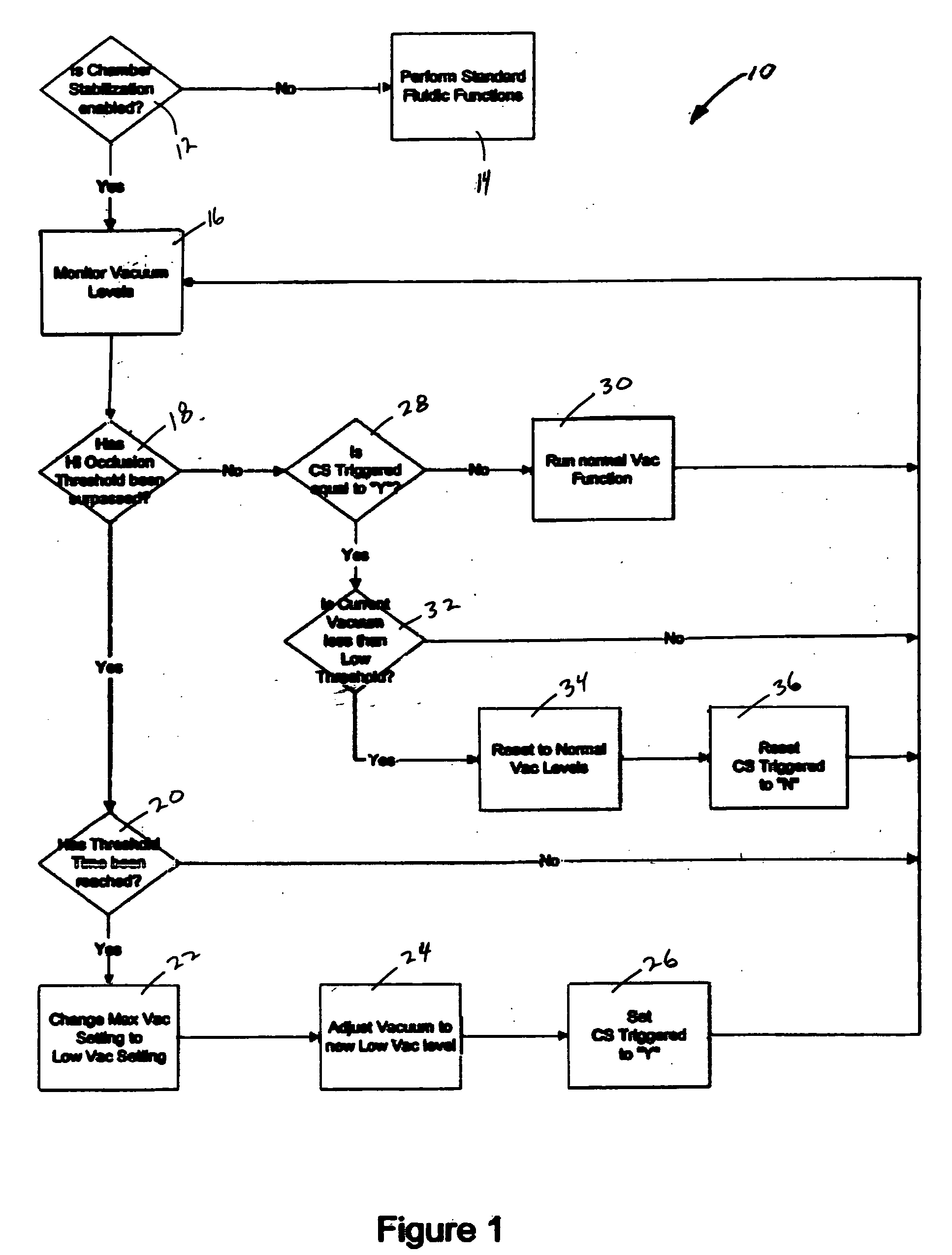
[0025] As illustrated in FIG. 1, a block diagram 10 sets forth a method in accordance with the present invention. It should be appreciated that the present method applies to controlling at least one of: 1) the supplied irrigation fluid, 2) vacuum, 3) aspiration rate, and 4) the power applied to a handpiece in an ophthalmic surgery procedure. Only one of the control features being set forth for the sake of brevity. The aspiration force may be provided by any type of fluid pump, including flow pumps and vacuum pumps.

[0026] As shown in FIG. 1, a system or method may include a pre-determined or user-chosen setting (for example, a setting labeled here as “Chamber Stabilization” or “CS”) to turn on or off the various embodiments of the present invention. If a user turns off this CS setting (i.e. CS is not enabled (12)), then standard fluidic functions (14) are performed without the benefit of the embodiments described herein.

[0027] In accordance with a method of the present invention du...


PUM


Abstract

A method for operating a surgical system including a control unit having a vacuum sensor and/or a flow rate sensor, the method including placing a handpiece in an operative relationship with an eye for a surgical procedure and thereafter supplying irrigation fluid to the handpiece while applying a vacuum to the handpiece to aspirate the irrigation fluid from the eye through the handpiece. During fluid aspiration, a vacuum level and/or flow rate is sensed which corresponds to an occlusion of the handpiece and from the sensed vacuum level and/or flow rate, a duration of the occlusion is determined. In response to the determined duration of occlusion, at least one of the handpiece parameters is varied.

Description

[0001] Embodiments of the present invention are generally directed to surgical methods and are more particularly directed to controlling the flow of fluid to and from a patient through a fluid infusion and extraction system such as, for example, in ophthalmic surgery wherein surgical instruments such as electromechanical or pneumatically driven cutters as well as phacoemulsification instruments are commonly employed. These instruments require a source of fluid to infuse a surgical site and a source of negative pressure to evacuate the infused liquid and debris from the site. A pump is usually employed to generate negative pressure. Typical pumps are either flow pumps, such as, for example, peristaltic or scroll pumps, or vacuum pumps, such as, for example Venturi pumps, diaphragm pumps or rotary vane pumps. [0002] A number of medically recognized techniques are utilized for cataractic lens removal based on, for example, phacoemulsification, mechanical cutting or destruction, laser t...

Claims


Application Information

Patent Timeline
IPC IPC(8): A61M31/00
CPCA61M3/0283A61F9/00745A61M1/774
Inventor CLAUS, MICHAEL J.WONG, WAYNE S.REISIN, CARINA R.JANG, STEPHEN H.
Owner JOHNSON & JOHNSON SURGICAL VISION INC
Why Eureka
Try Eureka