
High expansion foam fire-extinguishing system

Inactive Publication Date: 2008-06-05
NOHMI BOSAI LTD
View PDF7 Cites 7 Cited by
  • Summary
  • Abstract
  • Description
  • Claims
  • Application Information

AI Technical Summary

Benefits of technology

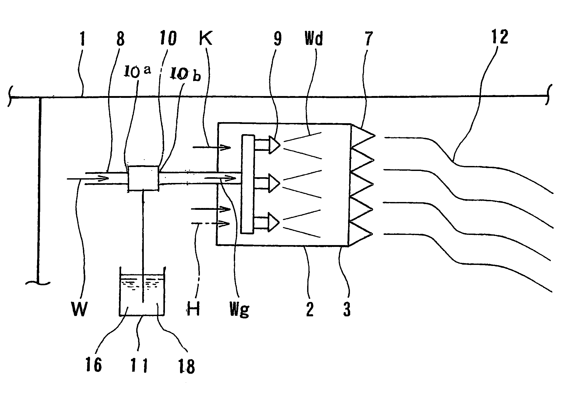
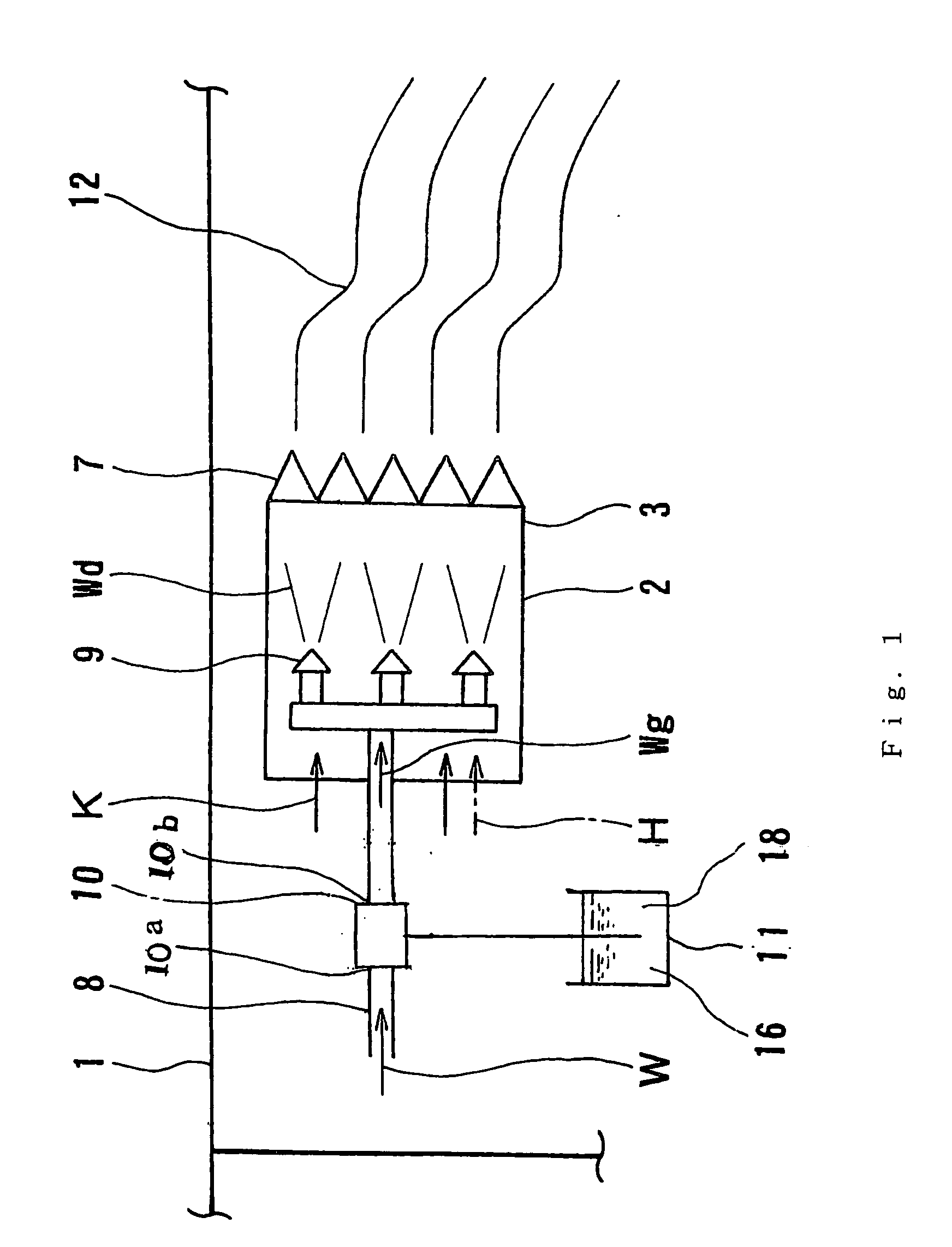
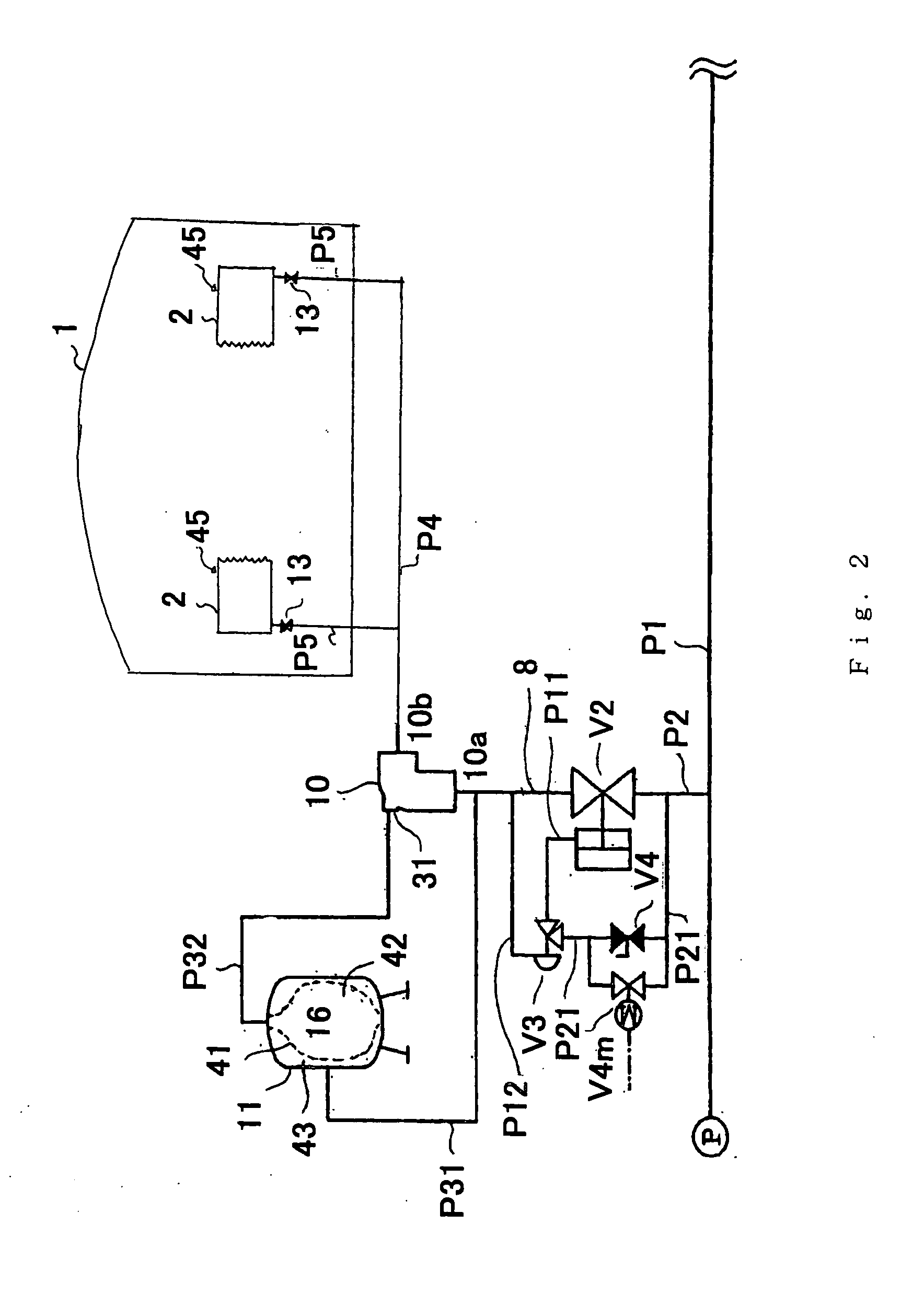
[0020]In the present invention, there is used a foam concentrate in which the mixing ratio of the foam concentrate with respect to the foam solution is an adjusted mixing ratio that is higher than the standard mixing ratio or in which the content rate of the surface active agent with respect to the foam concentrate is a design content rate that is higher than the standard content rate, with the mixing ratio of the surface active agent in the foam solution being the concentration for design foam expansion ratio, so even if smoke (smoke particles) is contained in the air in the discharge area, which is sucked into the flow passage, the foam solution foams at a desired foam expansion ratio. Thus, it is possible to obtain high expansion foam as designed, so it is possible to perform fire-extinguishing efficiently and reliably.
[0021]Usually, a aqueous film forming foam concentrate containing a fluorinated surfactant is mixed at the standard mixing ratio, and is used for low foam expansion ratio. This is due to the fact that the foaming property of the aqueous film forming foam concentrate is low, so the foam expansion ratio thereof at the standard mixing ratio is much lower than the foam expansion ratio of the synthetic surfactant foam fire extinguishing concentrate. However, even with this aqueous film forming foam concentrate, by attaining an adjusted mixing ratio higher than the standard mixing ratio, it is possible to obtain high foam expansion ratio. Further, the physical properties of the surface active agent are such that it exhibits low lipophilic nature except for the hydrophilic groups, and is little subject to the influence of smoke. Thus, the aqueous film formi

Problems solved by technology

However, in a system using outside air, in order to use air in the exterior, a duct is provided in the building, or a hole is formed in the partition wall to arrange a foam generator, resulting in a rather high cos

Method used


Image

  • High expansion foam fire-extinguishing system
  • High expansion foam fire-extinguishing system
  • High expansion foam fire-extinguishing system

Examples


Example

FIRST TEST EXAMPLE

[0081]In the high expansion foam fire-extinguishing system of the above-mentioned embodiment, a test was conducted under the following conditions, in which foaming was effected, with the mixing ratio of the MEGAFOAM F-623T (registered trademark) being higher than the standard mixing ratio (the adjusted mixing ratio), and the mixing ratio of the fluorinated surfactant with respect to the foam solution being the concentration for design foam expansion ratio. The test results are as shown in Table 1, in which the column of foam concentrate (%) shows adjusted mixing ratios, the column of fluorinated surfactant concentration (%) shows concentrations for design foam expansion ratio, and the column of foam expansion ratio shows actual foam expansion ratios.

[0082]As is apparent from Table 1, when, for example, the adjusted mixing ratio was 4.0%, the concentration for design foam expansion ratio was 0.4%, and the foam expansion ratio was 240, thus making it possible to obta...

Example

SECOND TEST EXAMPLE

[0087]In the second test example, instead of a aqueous film forming foam concentrate, a synthetic surfactant foam fire extinguishing concentrate was used as the foam concentrate, and a foaming test was conducted in the same manner as described above under the same test conditions as those of the first test example described above.

[0088]As the synthetic surfactant foam fire extinguishing concentrate, there was used SNOWRAP H (registered trademark) whose main ingredient is a hydrocarbon surfactant; the standard mixing ratio of this foam concentrate is 3%. The test results are as shown in Table 2, in which the column of foam concentrate (%) shows adjusted mixing ratios, the column of hydrocarbon surfactant concentration (%) shows concentrations for design foam expansion ratio, and the column of foam expansion ratio shows actual foam expansion ratios.

[0089]As is apparent from Table 2, when, for example, the adjusted mixing ratio was 4.0%, the concentration for design ...

Example

[0095]Next, a first embodiment of the second invention will be described with reference to FIGS. 3 and 4.

[0096]The first embodiment of the second invention differs from the embodiment of the first invention in the construction of the foaming apparatus (foam generator of this embodiment); otherwise, it is substantially of the same system construction as the above embodiment.

[0097]A high expansion foam fire-extinguishing system is provided in the room (chamber) 1 constituting the foam discharge area. This fire-extinguishing system is a foam generator equipped with the flow passage 2, with the foam expansion ratio thereof being set to 500. Inside the flow passage 2, there is provided the foaming portion 3 adapted to suck in the air of the discharge area 1.

[0098]At the foaming portion 3 at the forward end of the flow passage 2, there is provided the foam screen (screen) 7, on the inner side of which there are provided a plurality of emission nozzles 9 opposed to the foam screen 7 at an ...


PUM


Abstract

The present invention provides a high expansion foam fire-extinguishing system including: an emission nozzle (9) to which a foam solution (Wg) prepared by mixing water (W) with a foam concentrate (16) containing a surface active agent (18) is sent under pressure; a flow passage (2); and a foam screen (7) upon which the foam solution discharged from the emission nozzle impinges, in which the foam concentrate used is one of one in which a mixing ratio of the foam concentrate with respect to the foam solution is an adjusted mixing ratio higher than a standard mixing ratio and one in which a content rate of the surface active agent with respect to the foam concentrate is a design content rate that is higher than a standard content rate, and in which a mixing ratio of the surface active agent is a concentration for design foam expansion ratio.

Description

BACKGROUND OF THE INVENTION[0001]1. Field of the Invention[0002]The present invention relates to a high expansion foam fire-extinguishing system for use in various warehouses, hangars, plants where dangerous objects are handled, cabins, holds, etc., and more specifically, to a high expansion foam fire-extinguishing system which helps to prevent a reduction in foam expansion ratio.[0003]2. Description of the Related Art[0004]In a foam fire-extinguishing system, a foam solution (hereinafter also referred to simply as an “solution”) is discharged from an emission nozzle, and is caused to impinge upon a foam screen to absorb air to thereby generate foam, with which the source of a fire is covered, thereby effecting a fire-extinguishing by eliminating oxygen. Such a foam fire-extinguishing system is of two types: a low foaming fire-extinguishing system and a high foaming (high expansion foam) fire-extinguishing system.[0005]The above-mentioned two fire-extinguishing systems differ in foa...

Claims


Application Information

Patent Timeline
IPC IPC(8): A62C35/00
CPCA62C31/12A62C5/02
Inventor MURATA, SHINJIYOKOO, AKIHIKOASAMI, TAKASHI
Owner NOHMI BOSAI LTD
Learn More