
Method for forming RFID tags

a technology of rfid tags and rfid tags, which is applied in the near field of read/write/interrogation/identification systems, instruments, and semiconductor/solid-state device details, etc., can solve the problems of strap and antenna failure, additional layer of material to be placed, and requiring a much thicker strap substra

Inactive Publication Date: 2008-06-05
SQUARE 1 BANK
View PDF30 Cites 14 Cited by
  • Summary
  • Abstract
  • Description
  • Claims
  • Application Information

AI Technical Summary

Problems solved by technology

This mechanical stress can cause the interconnections between the strap and the IC 502 or strap and antenna to fail.
The drawback of this process is that an additional layer of material must be placed over the back side of the antenna substrate to protect the IC.
This also allows the strap to lie flat relative to the antenna substrate but has the disadvantage of requiring a much thicker strap substrate and the use of a more complicated assembly process to produce the strap.

Method used


Image

  • Method for forming RFID tags
  • Method for forming RFID tags
  • Method for forming RFID tags

Examples


Embodiment Construction

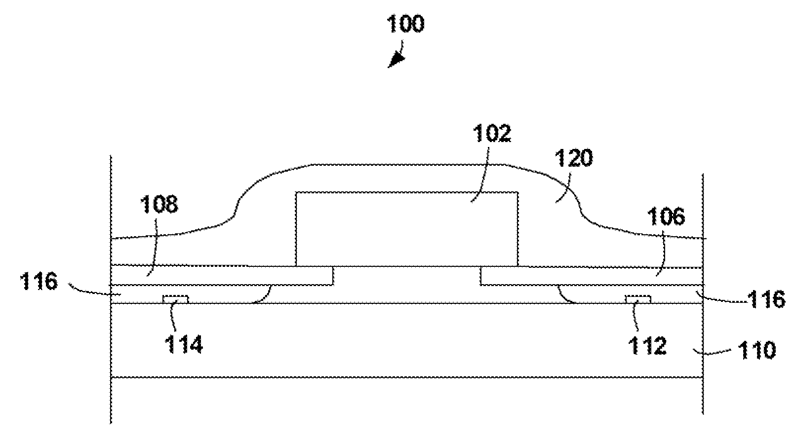
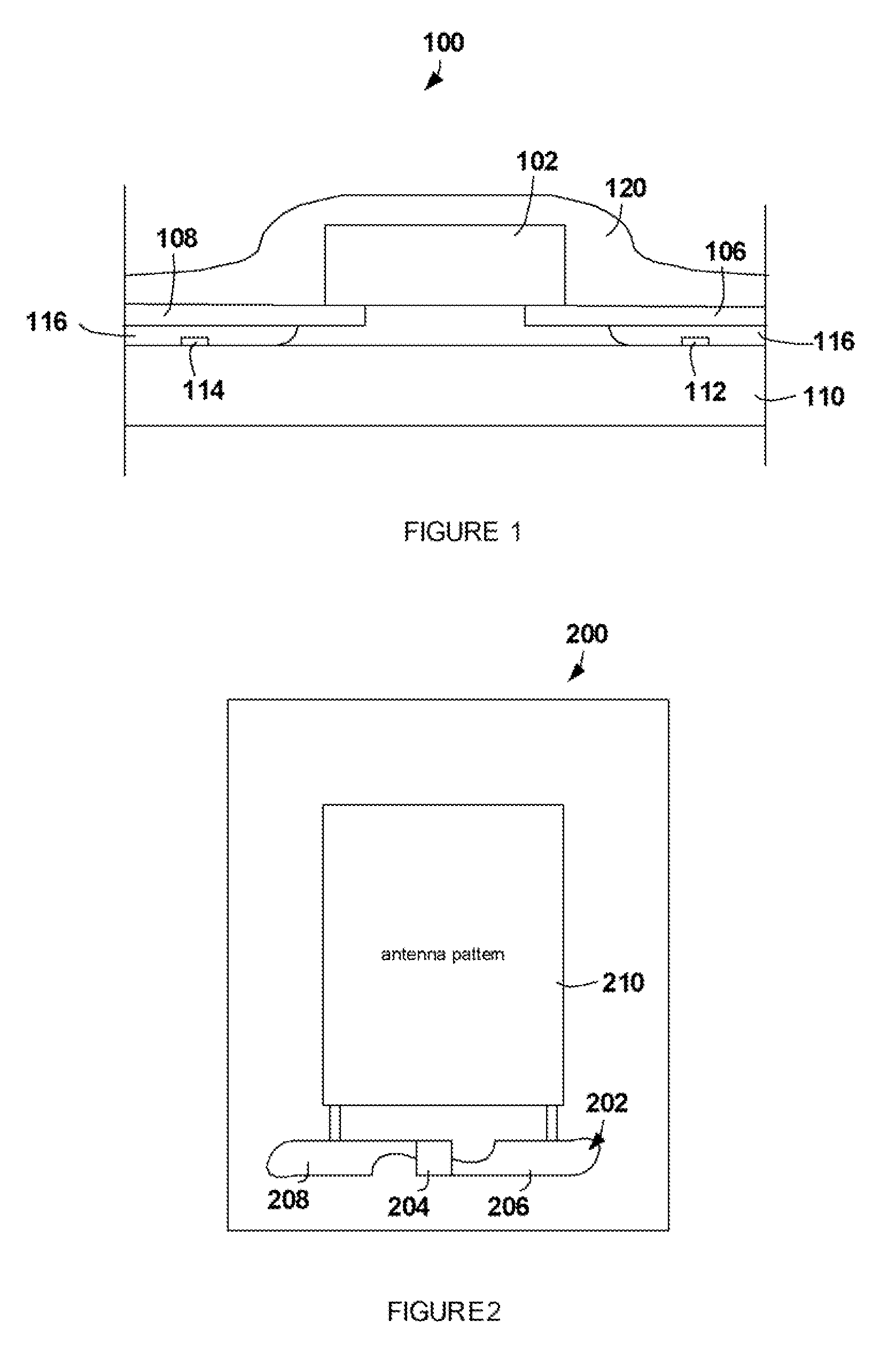
[0018]One embodiment of the present invention is a RFID tag including a tag substrate 602 with an antenna 604 and a strap substrate 606 with an IC 608, the strap substrate 606 positioned on the tags substrate, the IC 608 being electrically connected to the antenna 604 on the tag substrate 602 through a hole 610 and 612 in the strap substrate.

[0019]The hole 610 and 612 can be filed with a conductive material, such as a conductive adhesive. The conductive adhesive can be positioned on a bond pad of the tag substrate before the strap substrate is attached to the tag substrate. The conductive adhesive can alternately be placed in the hole after the strap substrate is attached to the substrate.

[0020]A strap can be produced with a small hole in the strap substrate in the region of the strap to antenna bond area 605. The strap can be assembled onto the antenna substrate with the chip facing up and away from the antenna substrate. This management means that the connections at bond area 605 ...


PUM


Abstract

A method of constructing an RFID unit can include using a protective layer to hold an integrated circuit chip module to a substrate layer with an antenna unit while a conductive adhesive has not yet fully set.

Description

CLAIM OF PRIORITY[0001]This application claims priority from the following co-pending applications, which are hereby incorporated in their entirety:[0002]U.S. Provisional Application No. 60 / 803,070 entitled “METHOD FOR FORMING RFID TAGS”, by Robert R. Oberle, filed May 24, 2006 (Attorney Docket No. RCDT-01010US0).BACKGROUND OF INVENTION[0003]Radio Frequency Identification (RFID) tags are typically small objects that can be attached to or incorporated into a product. RFID tags contain antenna to enable them to receive and respond to radio-frequency queries from an RFID tranciever. The RFID tags are used in a host of industries for purposes such as inventory control, security, personal identification and the like.[0004]The RFID tags can be passive or active. Active devices have their own power supply. Passive devices rely on energization from the RFID tranciever. Passive and active RFID tags can use integrated circuit chips to modulate the identification response.[0005]The constructio...

Claims


Application Information

Patent Timeline
Patent Type & Authority Applications(United States)
IPC IPC(8): H04B7/00H01L21/58
CPCG06K19/0775H01L21/56H01L2924/07811H01L2224/29101H01L2924/0665H01L2924/014H01L2224/2919H04B5/0068H04B5/0062H04B5/00H01L2924/14H01L23/49855H01L24/29H01L24/83H01L2223/6677H01L2224/7565H01L2224/838H01L2924/0102H01L2924/01047H01L2924/01082H01L2924/00H04B5/45H04B5/77
Inventor OBERLE, ROBERT R.
Owner SQUARE 1 BANK
Learn More