Electromagnetic Pen With Amplitude-Controlled Inking Function
- Summary
- Abstract
- Description
- Claims
- Application Information
AI Technical Summary
Benefits of technology
Problems solved by technology
Method used
Image
Examples
Embodiment Construction
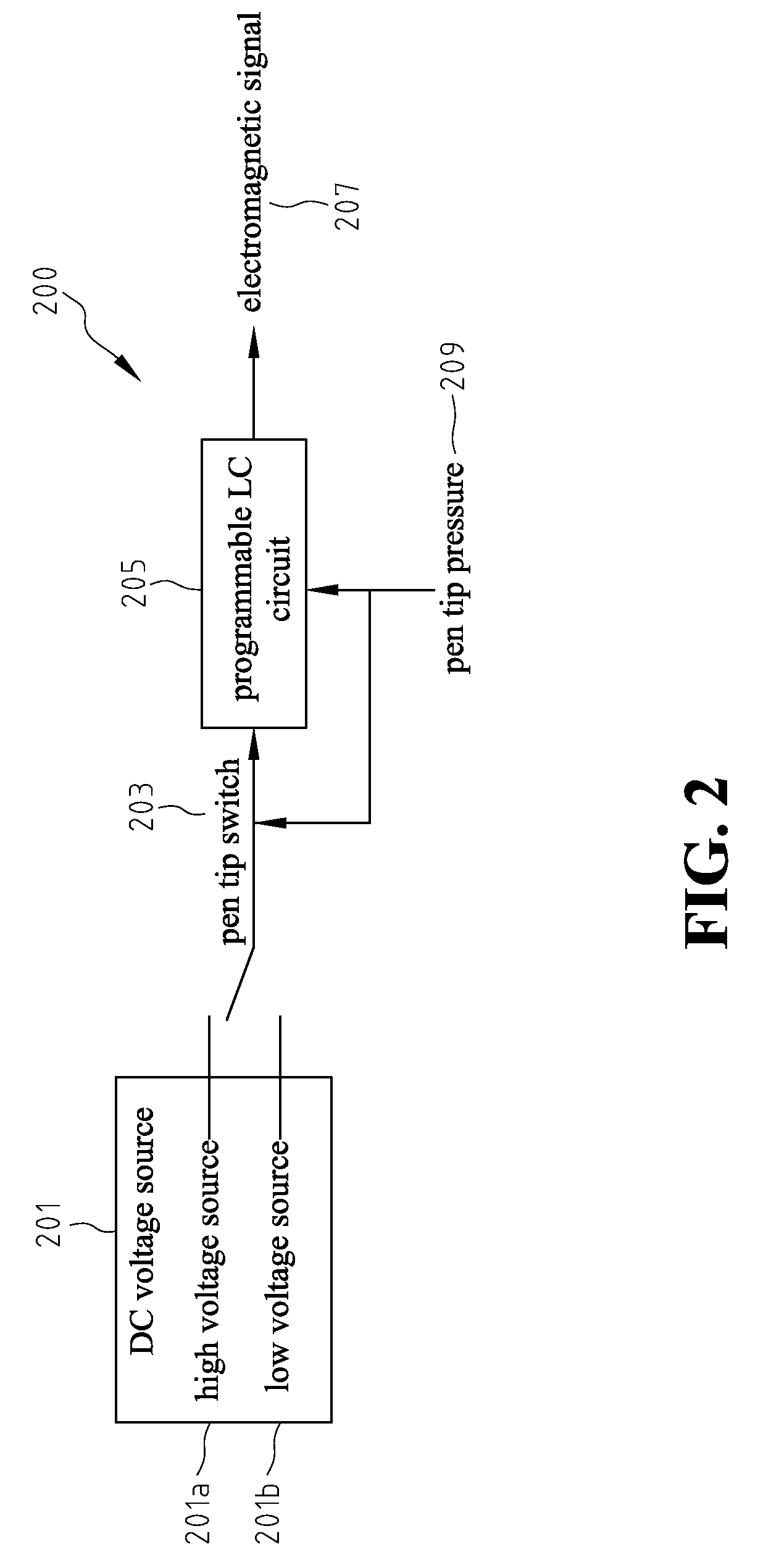
[0015]FIG. 2 shows a schematic view of the functional circuit block diagram of an electromagnetic pen of the present invention. A circuit 200 includes a DC voltage source 201 with a high voltage source 201a and a low voltage source 201b, a pen tip switch 203, and a programmable LC circuit 205. Pen tip switch 203 receives a pen tip pressure 209, and accordingly pen tip switch 203 determines whether to adopt high voltage source 201a or low voltage source 201b from DC voltage source 201, for DC voltage input of the LC circuit.
[0016]Pen tip switch 203 of the present invention can be a pressure-sensitive switch, a spring switch, a conductive rubber switch, or a membrane switch.
[0017]Pen tip switch 203 passes the determined DC voltage to programmable LC circuit 205. Programmable LC circuit 205 receives DC source from pen tip switch 203 and pen tip pressure 209, and outputs an electromagnetic signal 207 carrying information in both amplitude and frequency.
[0018]Electromagnetic signal 207 o...
PUM
 Abstract
Description
Claims
Application Information
 - R&D
- Intellectual Property
- Life Sciences
- Materials
- Tech Scout
- Unparalleled Data Quality
- Higher Quality Content
- 60% Fewer Hallucinations
Browse by: Latest US Patents, China's latest patents, Technical Efficacy Thesaurus, Application Domain, Technology Topic, Popular Technical Reports.
© 2025 PatSnap. All rights reserved.Legal|Privacy policy|Modern Slavery Act Transparency Statement|Sitemap|About US| Contact US: help@patsnap.com


