Optical network node device

a network node and optical fiber technology, applied in the field of network, can solve the problems of wss based, unable to connect to an optical fiber in a direction other than input/output, and unable to meet the requirements of optical fiber network nodes

Inactive Publication Date: 2008-06-05
ELECTRONICS & TELECOMM RES INST
View PDF5 Cites 22 Cited by
  • Summary
  • Abstract
  • Description
  • Claims
  • Application Information

AI Technical Summary

Problems solved by technology

Since the PLC based ROADM or the blocker based ROADM are basically a 4-terminals device, it is impossible to be connected to an optical fiber in a direction other than input / output.
The WSS based ROADM can be used in a node of at least degree 3, but is quite expensive compared to the PLC based or blocker based ROADM, and has weak durability.

Method used


Image

  • Optical network node device
  • Optical network node device
  • Optical network node device

Examples


Embodiment Construction

[0033]Hereinafter, the present invention will be described more fully with reference to the accompanying drawings, in which exemplary embodiments of the invention are shown.

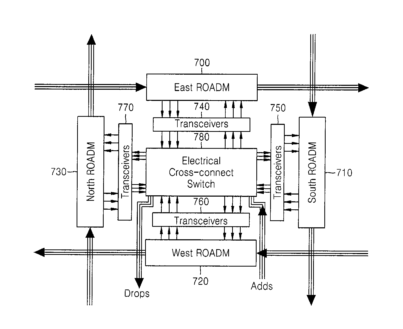
[0034]FIG. 7 is a diagram illustrating an optical network node device according to an embodiment of the present invention. In FIG. 7, an example of realizing a node of at least degree 3 by using a planar lightwave circuit (PLC) based or a blocker based reconfigurable optical add drop multiplexer (ROADM) of degree 2.

[0035]4-terminals ROADMs 700, 710, 720, and 730 control a wavelength division multiplexing (WDM) channel to pass through, drop, or pass through after adding an optically converted signal to the WDM channel.

[0036]Optical transceivers 740, 750, 760, and 770 photoelectrically convert a signal dropped from a corresponding ROADM or optically convert an electric signal transmitted to a corresponding ROADM.

[0037]Also, an electrical cross connect switch 780 switches the signal that is photoelectrically convert...


PUM


Abstract

Provided is an optical network node device. According to the optical network node device, a planar lightwave circuit (PLC) based or a blocker based 4-terminals ROADM can be used in a node of at least degree 3, a proceeding direction of a wavelength channel can be changed in an electrical cross connect switch, and transmission in a unit smaller than a wavelength channel can be cross connected, dropped, and added, or transmission capacity can be redistributed in the electrical cross connect switch. Accordingly, efficient transmission in a small capacity and large capacity transmission of a wavelength channel can be performed simultaneously, and thus an optical network can be effectively managed. Also, since the node of at least degree 3 uses the PLC based or a blocker based reconfigurable optical add drop multiplexer (ROADM), the node of at least degree 3 can use the same ROADM module as a node of degree 2. Accordingly, the optical network node device has an advantage in manufacturing and managing a node.

Description

CROSS-REFERENCE TO RELATED PATENT APPLICATION[0001]This application claims the benefit of Korean Patent Application Nos. 10-2006-0122554, filed on Dec. 5, 2006, and 10-2007-0099368, filed on Oct. 2, 2007, in the Korean Intellectual Property Office, the disclosures of which are incorporated herein in their entirety by reference.BACKGROUND OF THE INVENTION[0002]1. Field of the Invention[0003]The present invention relates to a network, and more particularly, to an optical network node using a reconfigurable optical add drop multiplexer (ROADM).[0004]The present invention is supported by the IT R&D program of MIC / IITA. [2006-S-059-01, ASON based Metro Photonic Cross-Connect Technology][0005]2. Description of the Related Art[0006]A wavelength division multiplexing (WDM) optical transmission technology is on the rise as a solution for satisfying remarkable increase of demand for high transmission capacity. The WDM optical transmission technology can simultaneously transmit several wavelen...

Claims


Application Information

Patent Timeline
Patent Type & Authority Applications(United States)
IPC IPC(8): H04J14/02
CPCH04J14/0206H04J14/0212H04J14/0217H04Q2011/0016H04J14/0221H04Q11/0005H04Q2011/0015H04J14/022
Inventor CHANG, SUN HYOKCHUNG, HWAN SEOKLEE, SANG SOOKIM, KWANGJOON
Owner ELECTRONICS & TELECOMM RES INST
Why Eureka
Try Eureka