Weight adjustable golf club head

a golf club head and adjustable technology, applied in the field of golf club heads, can solve the problems of affecting the fixation effect, so as to achieve the effect of enhancing the fixation

Inactive Publication Date: 2008-06-05
HSIAO PEN LONG
View PDF45 Cites 66 Cited by
  • Summary
  • Abstract
  • Description
  • Claims
  • Application Information

AI Technical Summary

Benefits of technology

[0005]Each weight member contains at least a weight element and a fastening element. The fastening element has a threaded rod extending from the bottom of a cone-shaped head. The fastening element is squeezed into an end of the weight element with the threaded rod penetrating through the we

Problems solved by technology

However, these approaches require that the club heads to be formed in high precision and the formation of the bolt holes is quite demanding in terms of both production time and effort.
Any slight deviation in the manufacturing process will render the club head useless, thereby significantly increasing the resource consumption and production cost.
It is because of these manufacturi

Method used


Image

  • Weight adjustable golf club head
  • Weight adjustable golf club head
  • Weight adjustable golf club head

Examples


first embodiment

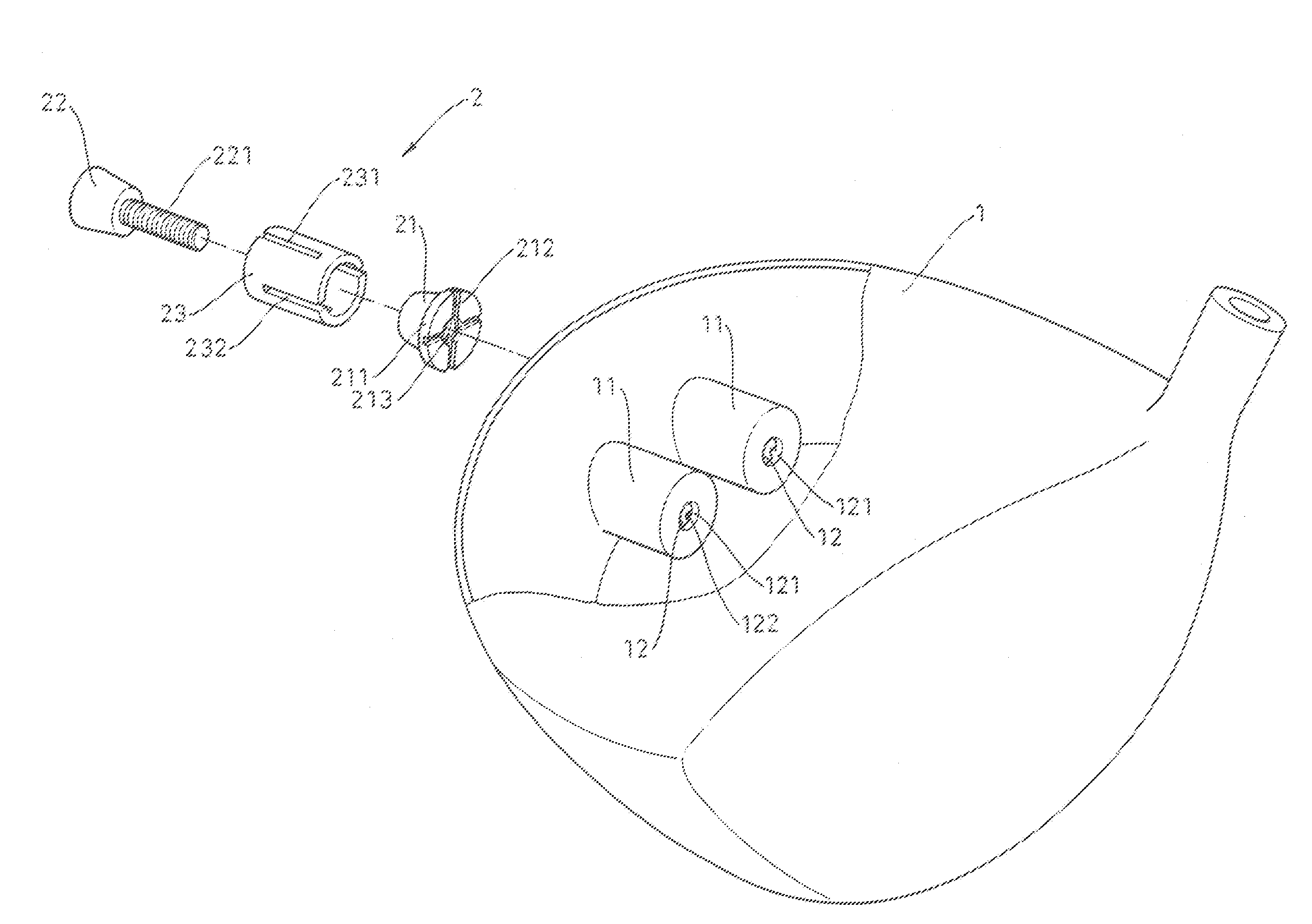
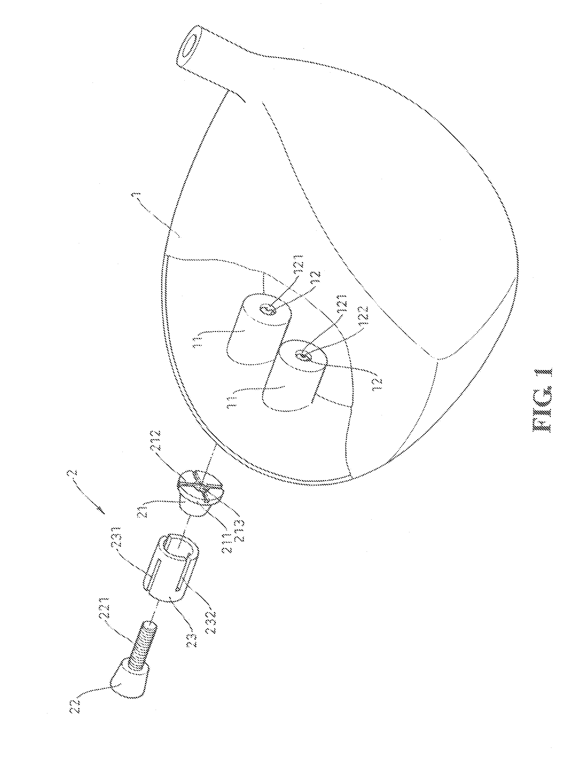
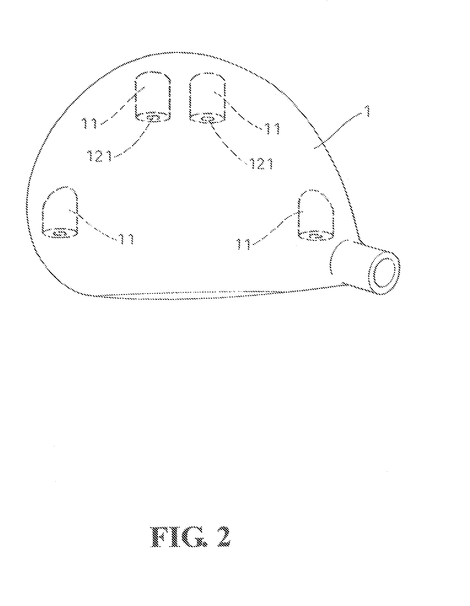
[0016]As shown in FIGS. 1 and 2, a club head 1 according to the present invention has a number of cylindrical blind holes 11 of appropriate depths into the interior of the club head 1 configured on the back surface (i.e., the curved surface opposite to the hitting surface of the club head 1) with appropriate spacing among them. Each of the blind holes 11 therefore provides a storage space 12 for the accommodation of a weight member 2.

[0017]The weight member 2 contains a tubular weight element 23, and a fastening element 22 and a seat element 21 plugged into the two ends of the weight element 23, respectively. The diameter of the weight element 23 is slightly smaller than the aperture of the blind hole 11 so that the weight element 23 can be slid into the blind hole 11. Along the circumference of the weight element 23, a member of through slits 231 are provided along the axial direction from a first end towards the other, second end (but not reaching the second end). Similarly, a num...

second embodiment

[0022]As shown in FIG. 6, a club head 1A according to the present invention has the blind holes 1A1 with longer depths than those of the previous embodiment. Inside the storage space 1A2 of each blind hole 1A1, two opposing slots 1A23 and 1A24 are provided along the axial direction and along the inner wall of the blind hole 1A1. Correspondingly, two radially protruding tenons 2A14 and 2A15 are provided on the rim of the base 2A11 of the seat element 2A1. As such, the seat element 2A1 is prevented from rotation when the fastening element 2A2 is screwed. In the present embodiment, there are multiple fastening elements 2A2, each having a threaded rod 2A21 of a specific length. When a particular fastening element 2A2 is used and screwed to join the seat element 2A1, the threaded rod 2A21 is able to run through the through channel 2A13 until its tip reaches the bottom of the blind hole 1A1. In the process, again, the slits 2A31 and 2A32 allows the two ends of the weight element 2A3 to ex...


PUM


Abstract

The club head contains a number of blind holes arranged at appropriate places other than the hitting surface of the club head. Each blind hole is for the accommodation of a weight member. Each weight member contains at least a weight element and a fastening element. The fastening element has a threaded rod extending from the bottom of a cone-shaped head. The fastening element is squeezed into an end of the weight element with the threaded rod penetrating through the weight element and into the club head for fixation. On the other hand, the circumference of the weight element has a number of slits so that the cone-shaped head of the fastening element can force the wall of the weight element to press tightly against the hole to further enhance the fixation.

Description

(A) TECHNICAL FIELD OF THE INVENTION[0001]The present invention generally relates to a golf club head, and more particularly to a golf club head whose center of gravity is adjustable.(B) DESCRIPTION OF THE PRIOR ART[0002]In recent years, as the manufacturing technologies for golf club heads continuously advance, large varieties of club heads of various forms and specifications are developed. The main purpose of all these new club head designs is nothing but to help golfers to hit the balls farther and more accurately. However, a golfer's performance still has a very large part related to the golfer's stance and habit.[0003]Therefore, so-called “weight tunable club heads” are developed and claimed to be able to adjust the club head's center of gravity to best suit a golfer's stance and habit. These “weight tunable club heads” generally have a number of fixed positions arranged on the club head and weights in the form of bolts are inserted or taken out so as to adjust the club head's ...

Claims


Application Information

Patent Timeline
IPC IPC(8): A63B53/00
CPCA63B2053/0491A63B53/0466A63B60/02
Inventor HSIAO, PEN-LONG
Owner HSIAO PEN LONG
Why Eureka
Try Eureka