
Array of graduated pre-tilted MEMS mirrors

a technology of pre-tilting and mirrors, applied in the field of optical systems, can solve the problems of less than optimum design for other considerations, and achieve the effects of reducing voltage requirements, reducing angular displacement requirements relative to the rest position of the micromirror, and increasing the number of addressable points

Inactive Publication Date: 2008-06-12
GLIMMERGLASS NETWORKS
View PDF4 Cites 27 Cited by
  • Summary
  • Abstract
  • Description
  • Claims
  • Application Information

AI Technical Summary

Benefits of technology

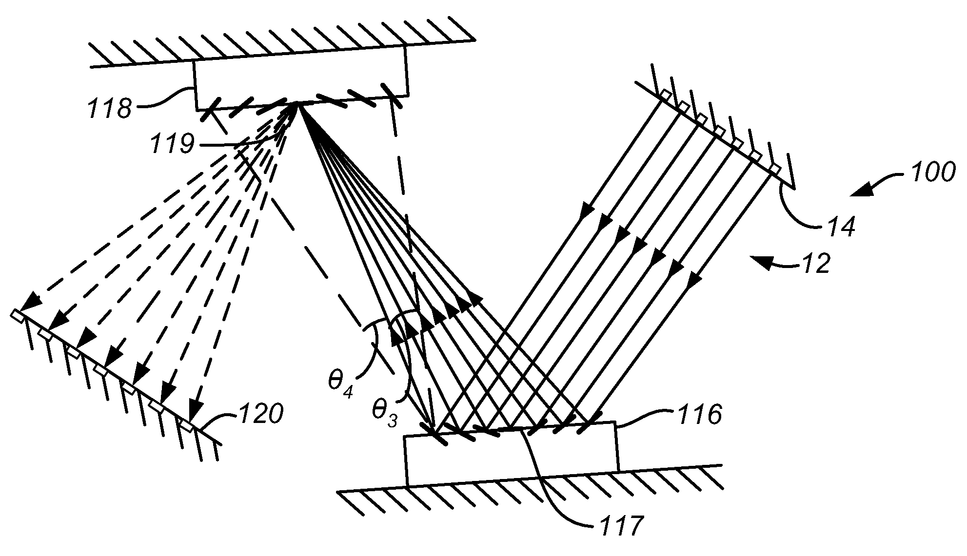
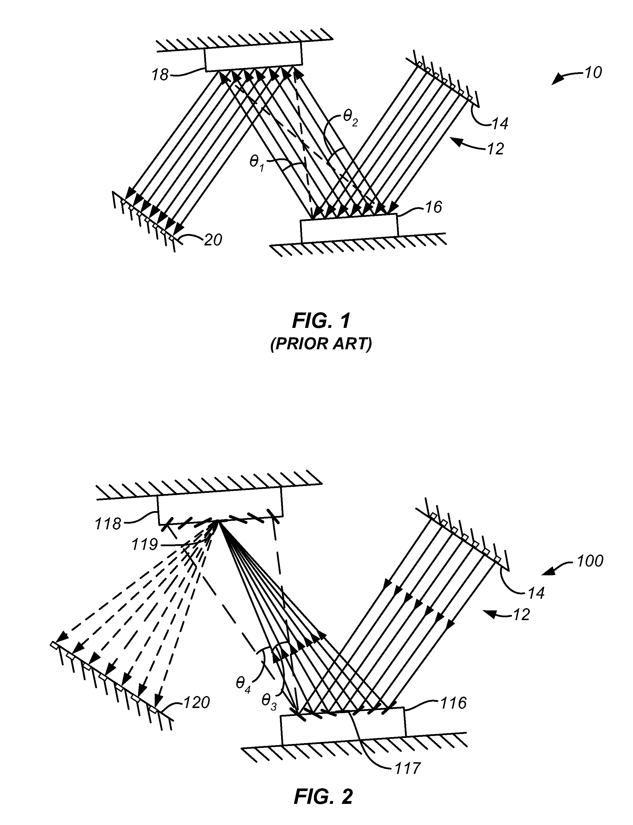
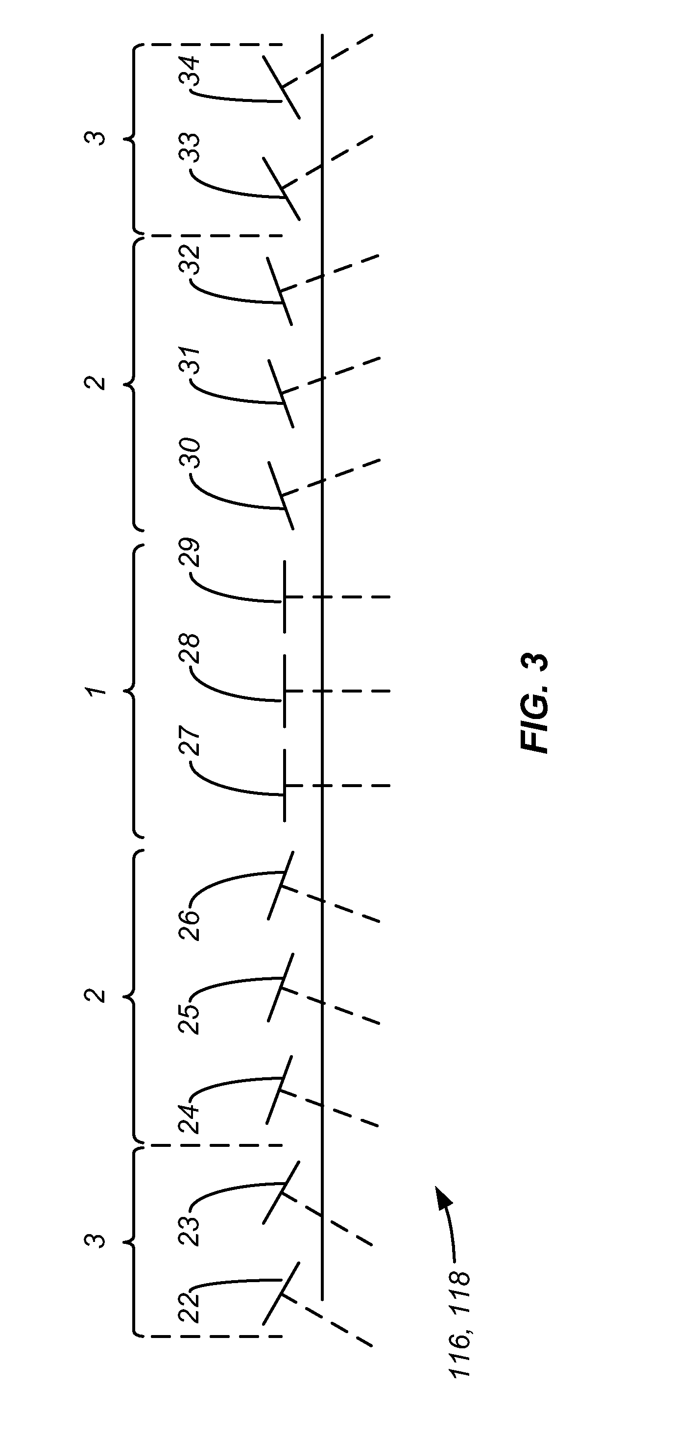
[0013]According to the invention, an array of MEMS devices is formed on a planar substrate having in each of a plurality of annular regions or sectors a plurality of MEMS mirrors of substantially identical structure, wherein the MEMS mirrors in each annular region have an identical pre-tilt. In a specific embodiment, the pre-tilt is achieved by embedding each dual-axis tiltable mirror within a pre-tilted microplatform or gimbal. One microplatform of a preselected pre-tilt is provided for each micromirror, and an underlying electrode is provided having a shape that accommodates the pre-tilt. In a specific embodiment, the annular regions are contiguous elliptical or oval regions. By pre-tilt, it is meant that the rest state or nonactuated or voltage-off state of the micro-mirror is tilted relative to the plane of the supporting structure or substrate such that a reflected beam from a fixed source to any micromirror at rest is directed substantially to the center of a target array of micromirrors. By pretilting the micromirrors, the angular displacement requirement relative to the rest position of the micromirror is reduced and as a consequence, either the mirror can be made stiffer and thus faster or the voltage requirement can be reduced. Alternatively, if the relative angle remains the same, the number of addressable points can be increased for the same voltage and switch speed requirement.

Problems solved by technology

As a consequence, the design will be less than optimum for other considerations such as driver voltage requirements, resonance and response limitations affecting switching speed, mirror flatness, optical loss and the number of switchable ports achievable.

Method used


Image

  • Array of graduated pre-tilted MEMS mirrors
  • Array of graduated pre-tilted MEMS mirrors
  • Array of graduated pre-tilted MEMS mirrors

Examples


Embodiment Construction

[0023]Referring to FIG. 2, a MEMS switch 100 steer light beams 12 from an input array 14 to impinge at first fixed locations on a first MEMS array of mirrors 116 having pre-tilt according to the invention and are reflected, when at rest, to a corresponding central point 119 of an array of mirrors at fixed locations of a second MEMS array 118. The beams are then directed to various locations of an output array 120 in accordance with angle of incidence. To address all of the MEMS mirrors of MEMS array 118, the mirrors of array 116 at rest must be able to be tilted through a range of angles from θ3 at one extreme of each mirror tilt at one end of the array 116 to θ4 at the other extreme of the same end of the array 116. A similar mirror tilt displacement range is required at each mirror, which is an angle that approximately corresponds to the same displacement required by the center MEMS mirror 117 at the center of the MEMS array 116, so that the center mirror as well as all other MEMS...


PUM


Abstract

An array of MEMS devices is formed on a planar substrate having in each of a plurality of annular regions or sectors a plurality of MEMS mirrors of substantially identical structure, wherein the MEMS mirrors in each region have an identical pre-tilt. The pre-tilt is achieved by embedding each dual-axis tiltable mirror within a pre-tilted microplatform or gimbal. In a specific embodiment, one microplatform of a preselected pre-tilt is provided for each micromirror and an underlying electrode is provided having a shape conforming with the pre-tilt. In a specific embodiment, the annular regions are contiguous elliptical or ovoidal regions. By pre-tilt, it is meant that the rest state or nonactuated state of the micro-mirror is such that a reflected beam from a fixed source is directed to the center of a target array.

Description

CROSS-REFERENCES TO RELATED APPLICATIONS[0001]NOT APPLICABLESTATEMENT AS TO RIGHTS TO INVENTIONS MADE UNDER FEDERALLY SPONSORED RESEARCH OR DEVELOPMENT[0002]NOT APPLICABLEREFERENCE TO A “SEQUENCE LISTING,” A TABLE, OR A COMPUTER PROGRAM LISTING APPENDIX SUBMITTED ON A COMPACT DISK[0003]NOT APPLICABLEBACKGROUND OF THE INVENTION[0004]This invention relates to optical systems employing an array of micro-electromechanical system (MEMS) mirrors, and particular arrays of MEMS mirrors which are electrically actuated to cause tilting.[0005]MEMS mirrors are used in optical systems, for example in compact, multi-channel free-space optical cross-connect switches whereby switching is accomplished by tilting pairs of dual-axis MEMS mirrors. The performance parameters of the structures are subject to the tilt angle requirements of the optical system. A prior art 64 port cross-connect switch required the application of about 250VDC across each MEMS mirror to achieve a mere 3.6 degree angle displac...

Claims


Application Information

Patent Timeline
IPC IPC(8): G02B26/00
CPCG02B6/3556G02B26/0841G02B6/357
Inventor STAKER, BRYAN P.FERNANDEZ, ANDRESOWENS, WINDSOR E.KINDWALL, ALEXANDER P.
Owner GLIMMERGLASS NETWORKS
Learn More