
Tray origin positioning system and tray origin positioning method

A technology of origin positioning and origin position, applied in electrical components, semiconductor/solid-state device manufacturing, circuits, etc., can solve the problems of wasteful positioning of the origin position of the tray, low rotation speed of the tray 10, low work efficiency, etc., to reduce angular displacement, improve speed, improve work efficiency

Active Publication Date: 2015-04-15
BEIJING NAURA MICROELECTRONICS EQUIP CO LTD
View PDF5 Cites 8 Cited by
  • Summary
  • Abstract
  • Description
  • Claims
  • Application Information

AI Technical Summary

Problems solved by technology

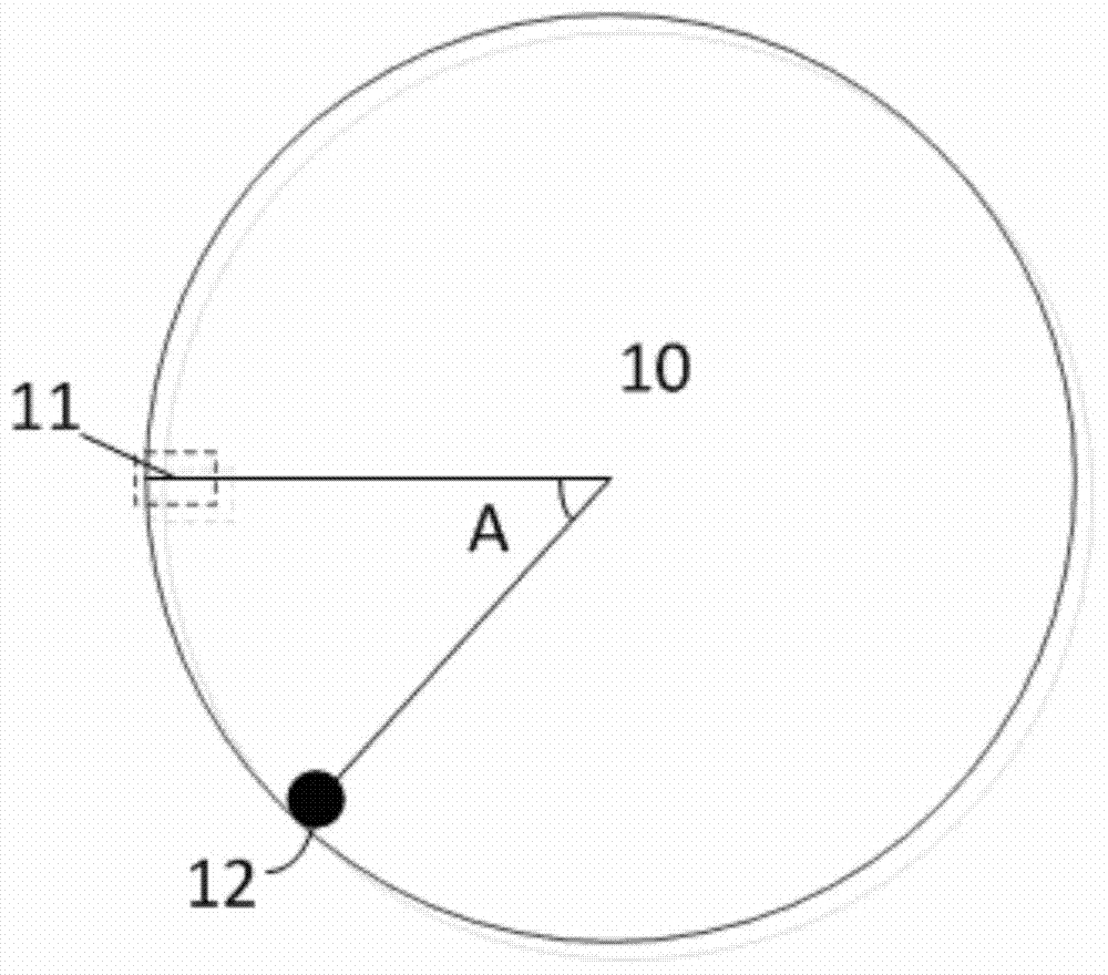
[0005] However, although the above-mentioned pallet origin positioning system can be used to accurately locate the pallet origin position, it inevitably has the following problems: figure 2 As shown, when the notch 11 is located in the clockwise direction at the corresponding position of the laser displacement sensor 12 on the tray 10, and the tray 10 rotates clockwise, the tray 10 needs to rotate a large angle (360 degrees - A degrees) to detect the notch 11 position, and the rotating speed of the pallet 10 is very low during the entire pallet origin positioning process, which requires a long time to locate the pallet origin position, causing the original positioning speed of the pallet to be too slow, resulting in low work efficiency

Method used


Image

  • Tray origin positioning system and tray origin positioning method
  • Tray origin positioning system and tray origin positioning method
  • Tray origin positioning system and tray origin positioning method

Examples


Embodiment Construction

[0027] In order to enable those skilled in the art to better understand the technical solution of the present invention, the pallet origin positioning system and pallet origin positioning method provided by the present invention will be described in detail below with reference to the accompanying drawings.

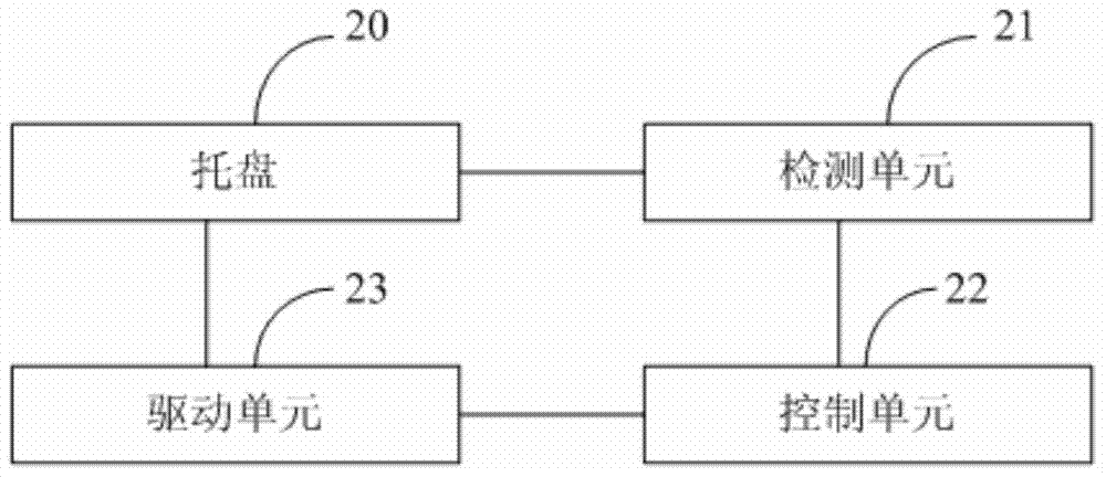
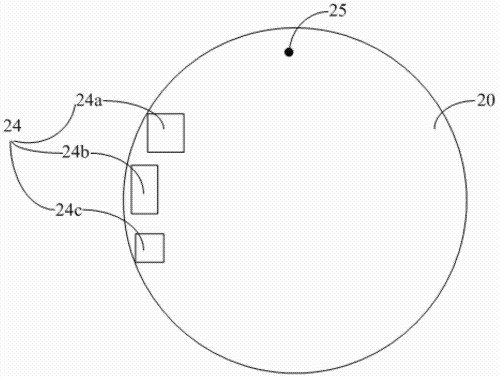
[0028] figure 2 It is a functional block diagram of the pallet origin positioning system provided by the first embodiment of the present invention. image 3 It is a schematic structural diagram of the pallet of the pallet origin positioning system provided by the first embodiment of the present invention. Please also refer to figure 2 and image 3 , the tray origin positioning system provided in this embodiment includes a tray 20 , a detection unit 21 , a control unit 22 and a drive unit 23 . Wherein, the tray 20 is a circular structure, and at least two reflectors 24 different from the reflectivity of the upper surface of the tray 20 are arranged on the upper surface...


PUM


Abstract

The invention provides a tray origin positioning system and a tray origin positioning method. The tray origin positioning method includes the steps: S1, driving a tray to rotate, transmitting a detection signal to a tray at a preset detection point, and receiving a reflected signal which is reflected when the upper surface of the tray rotates to the position corresponding to the preset detection point; S2, determining a reflecting portion reaching the position corresponding to the preset detection point first according to the reflected signal reflected by the upper surface of the tray, determining a rotating direction of the tray according to the preset positional relation of the preset detection point and the reflecting portion, judging whether the origin position is located in the forward direction of the rotating direction of the tray or not according to the corresponding relation of the position of the reflecting portion on the tray and the origin position, if yes, controlling a driving unit to drive the tray to continue rotating to the origin position, and if not, controlling the driving unit to drive the tray to reversely rotate to the origin position. By the tray origin positioning method, rate of tray origin positioning can be improved, and accordingly working efficiency is improved.

Description

technical field [0001] The invention belongs to the field of semiconductor equipment manufacturing, and in particular relates to a tray origin positioning [0002] System and pallet origin positioning method. Background technique [0003] Metal-organic Chemical Vapor Deposition (MOCVD for short) is a new type of vapor phase growth technology developed on the basis of vapor phase epitaxial growth. Specifically, the basic principle of MOCVD technology is to use organic compounds of group III and group II elements and hydrides of group V and group VI elements as raw materials for crystal growth, and perform vapor phase epitaxy on the processed workpiece in a thermal decomposition reaction mode, so that Various III-V and II-VI compound films are formed on the surface of the processed workpiece. After the process is completed, the automatically controlled manipulator is usually used to load and unload the processed workpiece. Before the loading and unloading process, the pallet...

Claims


Application Information

Patent Timeline
Patent Type & Authority Applications(China)
IPC IPC(8): H01L21/673H01L21/68
CPCH01L21/67346H01L21/68
Inventor 赵海洋
Owner BEIJING NAURA MICROELECTRONICS EQUIP CO LTD
Learn More