
Inking device adjustment method

a technology of inking device and adjustment method, which is applied in the direction of printing press, rotary press, printing press, etc., can solve the problems of inability to accurately adjust the position of the ink film pick-up roller relative to the inking roller, the disadvantage of being susceptible to the subjectivity of the operator, and the inability to accurately adjust the position of the ink film pick-up roller, etc., to achieve reliable and simple adjustment

Inactive Publication Date: 2011-07-26
GOSS INT MONTATAIRE
View PDF13 Cites 1 Cited by
  • Summary
  • Abstract
  • Description
  • Claims
  • Application Information

AI Technical Summary

Benefits of technology

[0013]An object of the invention is to overcome the disadvantages mentioned and to provide an inking device which allows a more reliable and simple adjustment in order to provide a regular supply of ink.
[0028]displacing the first shaft relative to the second shaft by reducing the actual angular displacement and / or by modifying the relative radial position of the first shaft relative to the second shaft.

Problems solved by technology

The positioning of the ink film pick-up roller relative to the inking roller is a very complex adjustment operation since it determines the homogeneity of the supply of ink to the medium to be printed which is generally constituted by a web of paper to be printed.
This adjustment has the disadvantages of being imprecise and being susceptible to the subjectivity of the operator.

Method used


Image

  • Inking device adjustment method
  • Inking device adjustment method
  • Inking device adjustment method

Examples


Embodiment Construction

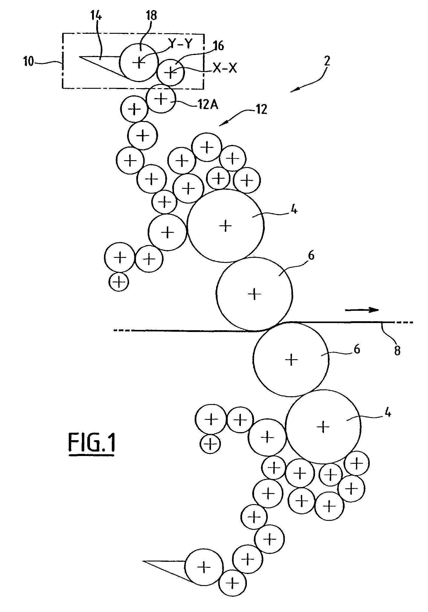
[0040]FIG. 1 illustrates a printing unit according to the invention, generally designated 2.

[0041]The printing unit 2 comprises a plate cylinder 4 and a blanket cylinder 6 which is capable of printing an image on a web 8 of paper which forms a medium to be printed.

[0042]The printing unit 2 is provided with an inking device 10, and a plurality of distributor rollers 12.

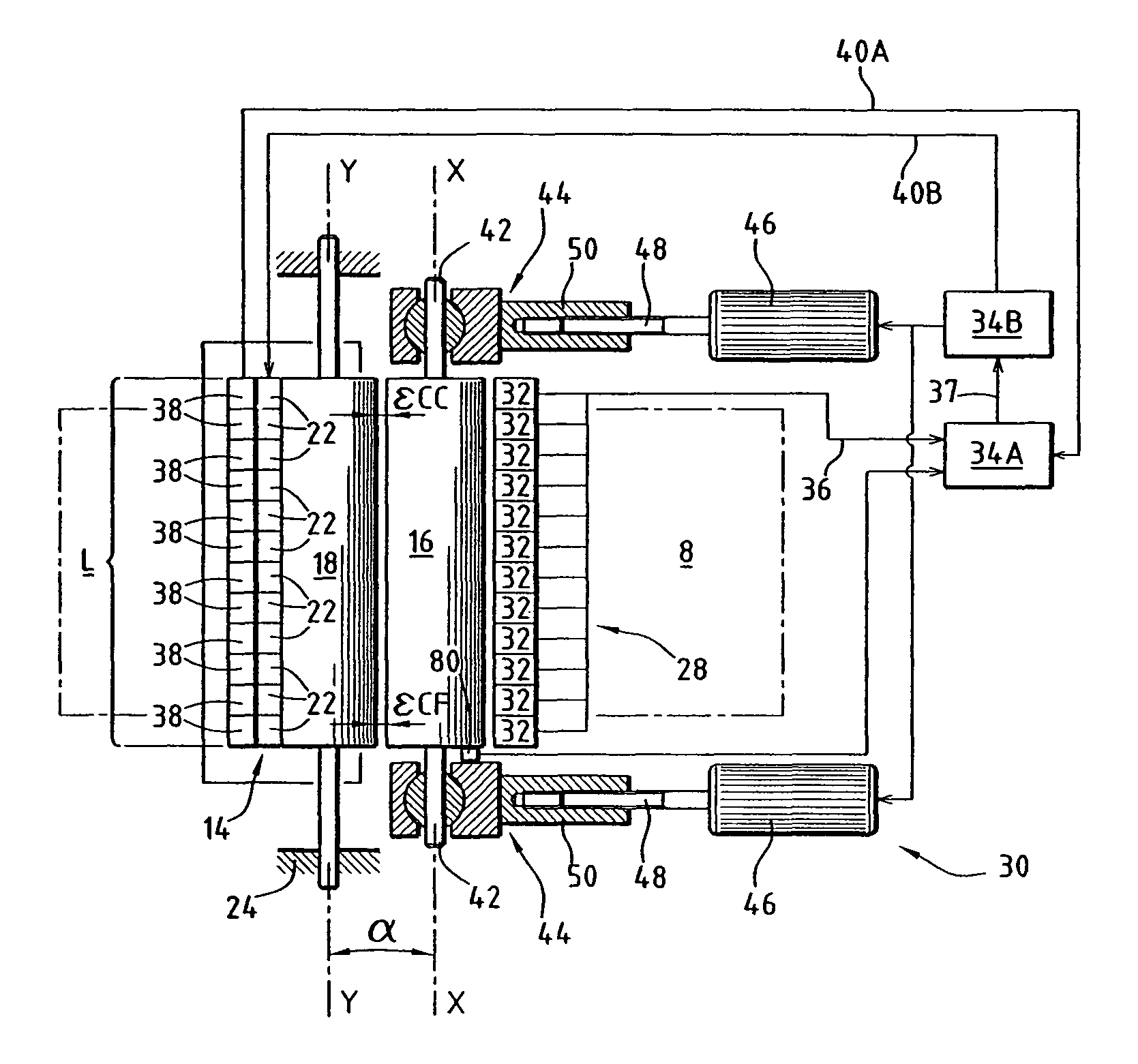
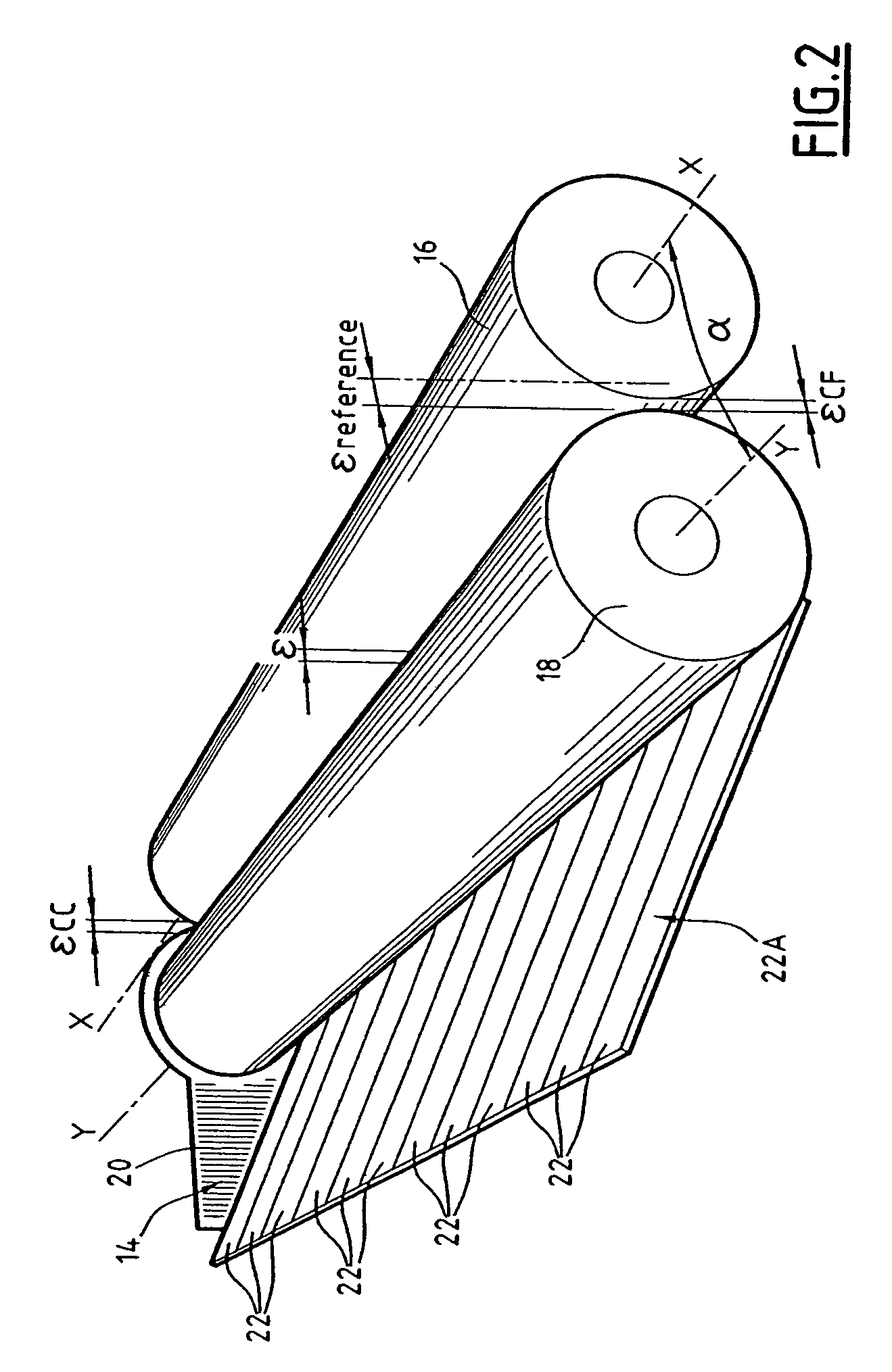
[0043]The inking device 10 is provided with an ink reservoir 14, an ink film pick-up roller 16 which can be rotatably moved about a first shaft X-X, and an inking roller 18 which is capable of transferring ink from the ink reservoir 14 to the pick-up roller 16 and which can be rotatably moved about a second shaft Y-Y.

[0044]As illustrated in FIG. 2, the ink reservoir 14 comprises two lateral plates 20, one of which is illustrated, and a plurality of adjustment screws 22 which can be moved and which allow the thickness of the ink transferred from the ink reservoir 14 to the inking roller 18 to be adjusted locally.

[0045]A...


PUM


Abstract

An inking device of a printing unit includes an ink reservoir, an ink film pick-up roller which has a shaft, and an inking roller having a shaft.A detector detects the distance between the inking roller and the pick-up roller and / or an angular displacement of the two shafts relative to each other and providing an output signal which represents this distance and / or this angular displacement. A controller angularly the second shaft relative to the first shaft, and the controller is capable of reducing the angular displacement and of positioning the pick-up roller in accordance with the output signal.

Description

[0001]This claims priority to French patent application number 0513273, filed Dec. 23, 2005, and hereby incorporated by reference herein.[0002]The present invention relates to an inking device of a printing unit, of the type comprising:[0003]a reservoir of ink,[0004]an ink film pick-up roller having a first shaft, and[0005]an inking roller which defines a printing width and which is capable of transferring ink from the ink reservoir to the ink film pick-up roller and which has a second shaft.[0006]It is used in particular in printing units of rotary offset presses.BACKGROUND[0007]Inking devices are known from the prior art which comprise an ink reservoir, an ink film pick-up roller which is capable of transferring ink to a distributor roller, and an inking roller which is capable of transferring ink from the ink reservoir to the ink film pick-up roller.[0008]The positioning of the ink film pick-up roller relative to the inking roller is a very complex adjustment operation since it d...

Claims


Application Information

Patent Timeline
Patent Type & Authority Patents(United States)
IPC IPC(8): B41F31/00
CPCB41F13/34B41F33/14
Inventor ROUSSEAU
Owner GOSS INT MONTATAIRE
Learn More