
Heat exchanger comprising bypass channels

A heat exchanger, bypass channel technology, applied in heat exchange equipment, heat exchangers, heat exchanger shells, etc., can solve problems such as large flow loss of exhaust gas

Inactive Publication Date: 2015-09-16
SCANIA CV AB
View PDF5 Cites 1 Cited by
  • Summary
  • Abstract
  • Description
  • Claims
  • Application Information

AI Technical Summary

Problems solved by technology

When the restrictor is in the closed position, the exhaust suffers a relatively large flow loss

Method used


Image

  • Heat exchanger comprising bypass channels
  • Heat exchanger comprising bypass channels
  • Heat exchanger comprising bypass channels

Examples


Embodiment Construction

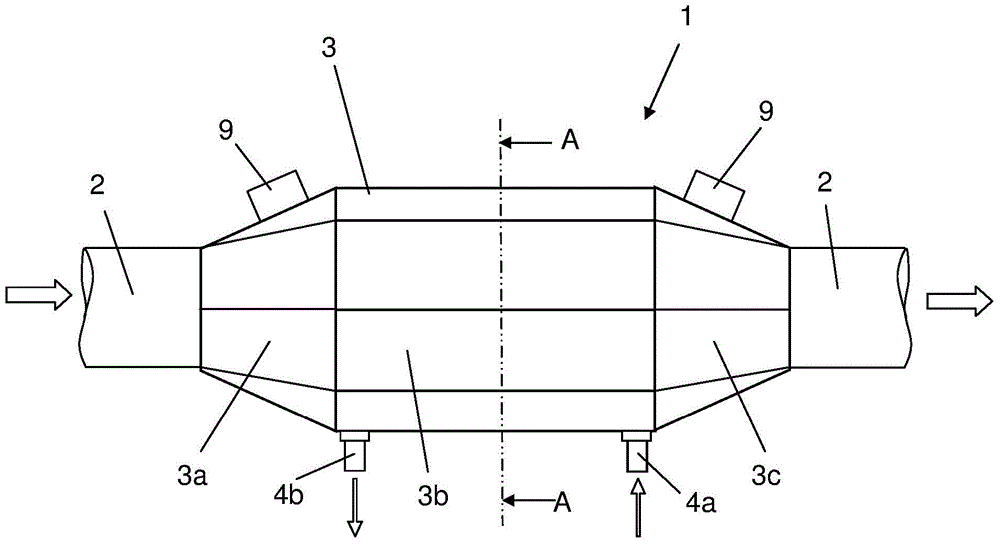
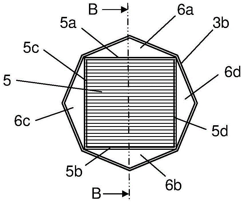
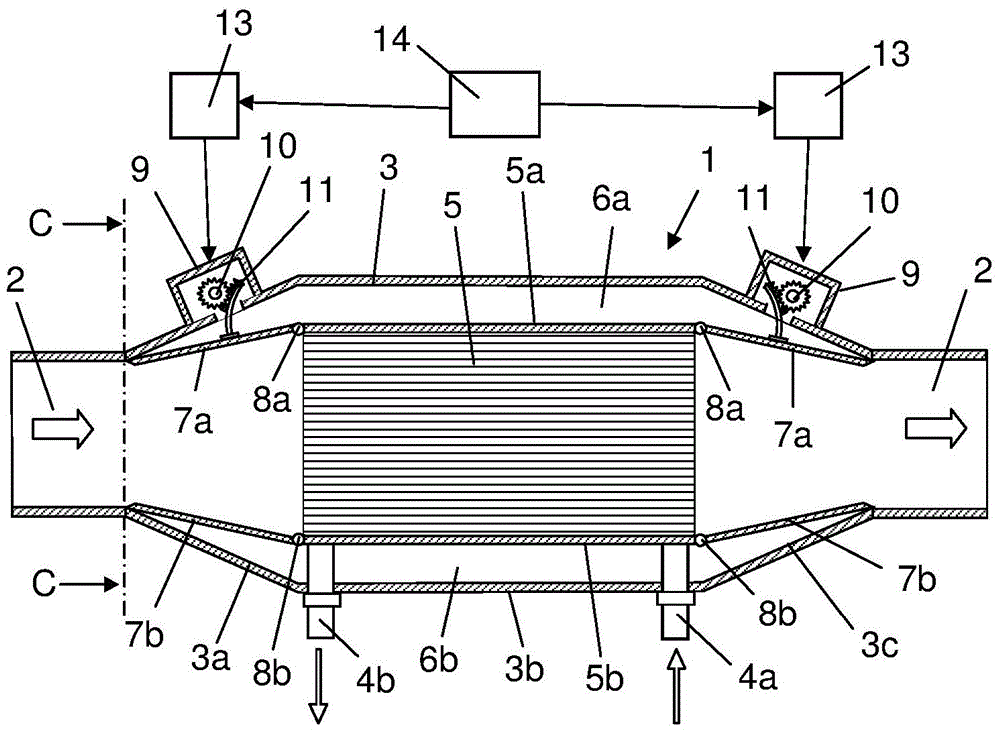
[0021] figure 1 A heat exchanger is shown. The heat exchanger is exemplified here as an intercooler 1 in a vehicle operated by a heavy-duty combustion engine. The first medium in the form of charge air is cooled in the intercooler 1 . The intercooler 1 is arranged inside an air line 2 which conducts charge air to the combustion engine. The intercooler 1 comprises a container 3 which forms the outer surface for the intercooler 1 . The container 3 is composed of an inlet section 3a, a middle section 3b and an outlet section 3c. The inlet section 3a has a continuously increasing cross-sectional area in the longitudinal direction starting from the connection to the part of the air line 2 arranged upstream of the intermediate section 3b. The middle section has a constant cross-sectional area. The outlet section 3 c has a continuously decreasing cross-sectional area in the longitudinal direction from the middle section 3 b to the connection to the part of the air line 2 positio...


PUM


Abstract

The present invention pertains to a heat exchanger comprising a container (3) which comprises an inlet section (3a), an intermediate section (3b) which encloses a heat exchanger device (5), and an outlet section (3c) where the first medium is led away from the heat exchanger device (5). The heat exchanger device (5) has a peripheral surface which in at least two areas is located at a distance from an internal surface in the container (3), so that at least two bypass channels (6a-d) are formed for the first medium next to the heat exchanger device (5). The heat exchanger comprises at least flow elements (7a-d) adapted to regulate the flow of the first medium through the bypass channels (6a-d). Each one of said flow elements (7a-d) has a first end section which is jointedly connected to the heat exchanger device (5) and a second free end section which is located at a distance from the heat exchanger device (5).

Description

technical field [0001] The invention relates to a heat exchanger according to the preamble of claim 1 . Background technique [0002] The amount of air that can be added to a heavy-duty combustion engine in a vehicle depends on the pressure of the air, but also on the temperature of the air. In order to add as much air as possible to a heavy-duty combustion engine, the charge air is cooled in an intercooler before it is led to the combustion engine. In conventional intercoolers, all charge air directed to the intercooler is cooled. However, in certain operating conditions it is desirable to eliminate or at least reduce cooling of the charge air. After eg a cold start of the vehicle, it is desirable that components used for exhaust aftertreatment, such as SCR catalysts, quickly achieve a temperature at which injection of urea solution can begin. In this case, cooling of the charge air delays heating of the SCR catalyst. In vehicles, it may also be desirable to regulate co...

Claims


Application Information

Patent Timeline
IPC IPC(8): F28F27/02F01N3/02F01P7/00F28D7/00F28F9/22F28F13/08
CPCF28F27/02F28D7/1684F28D2021/0082F01N3/02F28D21/0003F28F2250/06F01P7/00F28D7/00F02B29/0431F02M26/25F02M26/26F28D7/1653Y02T10/12F01P7/10F28D2020/0069F28D2020/0086F28F9/22F28F13/08
Inventor Z·卡多斯T·哈尔奎斯特
Owner SCANIA CV AB
Learn More