
LED light engine and method of manufacturing

Inactive Publication Date: 2008-06-12
GELCORE LLC (US)
View PDF13 Cites 20 Cited by
  • Summary
  • Abstract
  • Description
  • Claims
  • Application Information

AI Technical Summary

Benefits of technology

[0005]In accordance with one aspect of the present invention, a light emitting diode (LED) light engine includes at least one LED, the at least one LED having at least one first electrical terminal and at least one second electrical terminal. The LED light engine further includes an electrical cable having a first conductor and a second conductor, the at least one LED being secured to the first conductor by a first insulation displacement connector (IDC) and to the second con

Problems solved by technology

Current methods of manufacturing an LED light engine typically involve the time consuming assembly of multiple unique components to a suitable electrical cable.
Because the above described assembly process is repeated for each individual LED point light source on a LED light engine, the assembly process is not only tedious but requires a voluminous quantity of each component be kept on hand.
Maintaining such large inventories of components further adds to the overhead costs and financial burdens of a LED light engine manufacturer.

Method used


Image

  • LED light engine and method of manufacturing
  • LED light engine and method of manufacturing
  • LED light engine and method of manufacturing

Examples


Embodiment Construction

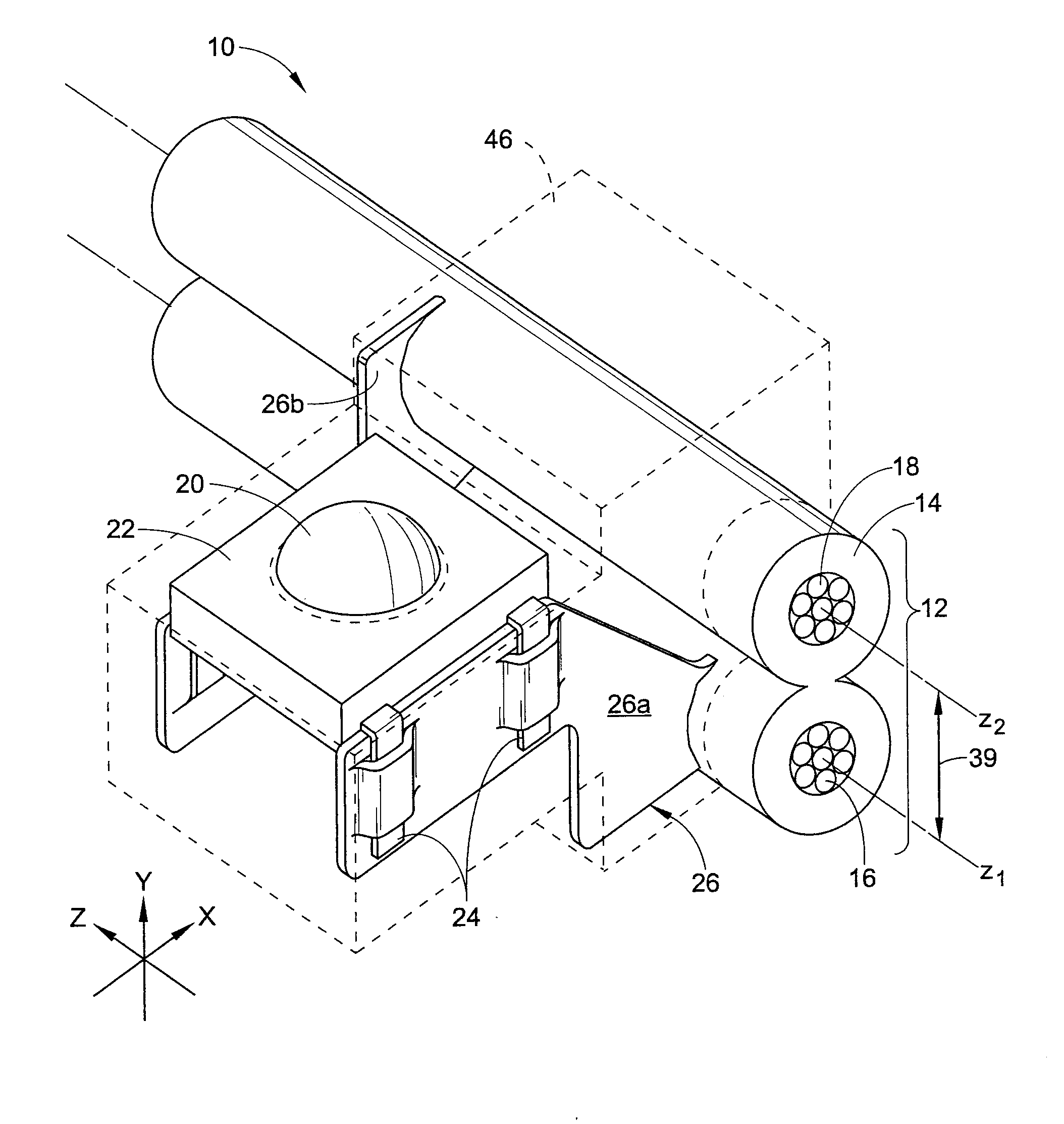
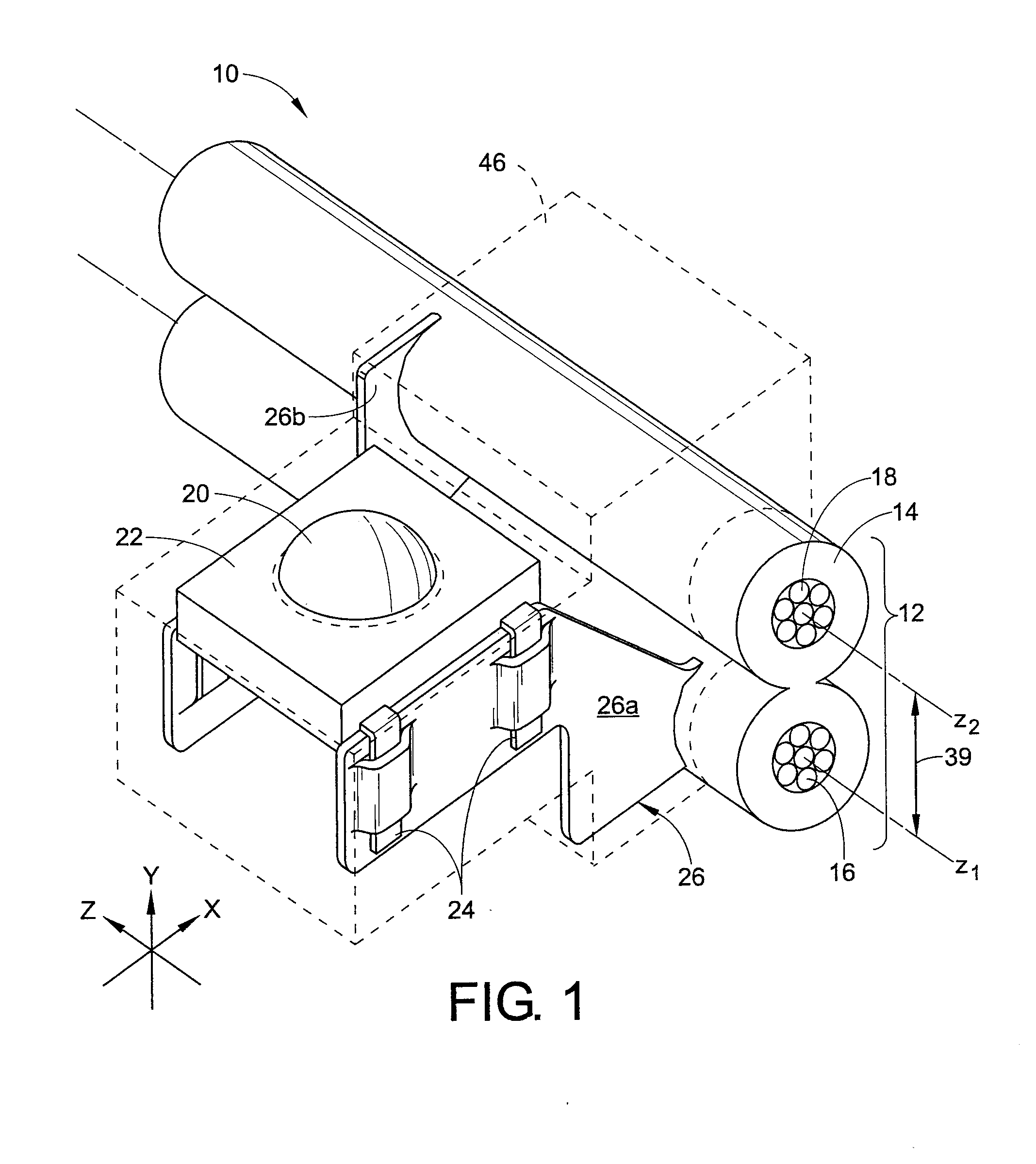
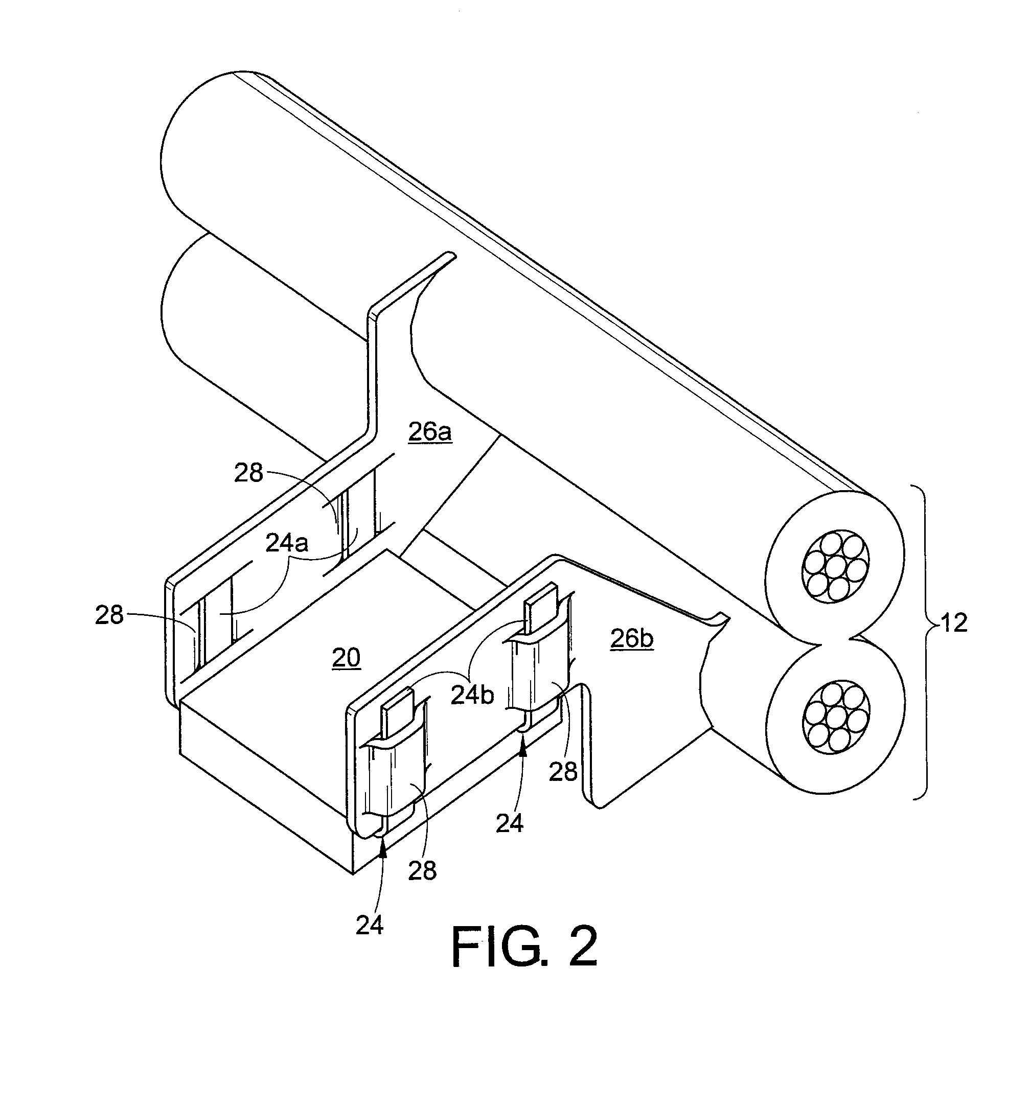
[0023]With reference to FIGS. 1-2, a light emitting diode (LED) light engine 10 includes a flexible electrical cable 12 surrounded by a flexible electrically insulating covering 14. Specifically, the cable 12 includes a plurality of substantially parallel conductors. In particular, the cable 12 includes a first conductor 16 having a longitudinal axis z1, as well as a second conductor 18 having a longitudinal axis Z2. Each of the conductors 16, 18 is electrically insulated by the insulating covering or portion 14. The insulating portion 14 may consist of any number of materials having non-conductive properties, such as rubber, PVC, silicone and / or EPDM. However, other materials can also be contemplated. Certain aspects of the LED light engine 10 will be described with reference to a typical three axis system. Generally, a Z axis is defined as being coincident with the longitudinal axis of the cable 12, an X axis is defined to be perpendicular to the Z axis in a horizontal plane, and ...


PUM


Abstract

The present invention relates to a light emitting diode (LED) light engine. The LED light engine includes at least one LED, the at least one LED having at least one first electrical terminal and at least one second electrical terminal. The LED light engine further includes an electrical cable having a first conductor and a second conductor, the at least one LED being secured to the first conductor by a first insulation displacement connector (IDC) and to the second conductor by a second IDC. The first IDC includes at least one socket for receiving the at least one first electrical terminal and a piercing portion for displacing the insulating portion and electrically contacting the first conductor of the electrical cable. The second IDC includes at least one socket for receiving the second terminal of the at least one LED and a piercing portion for displacing the insulating portion and contacting the second conductor of the electrical cable.

Description

BACKGROUND[0001]The present invention relates generally to the field of lighting systems. It finds particular application in conjunction with light emitting diode (LED) strips and will be described with particular reference thereto. It will be appreciated, however, that the invention is also amenable to other like applications.[0002]LED lighting strips or light engines are known in the art for their use in various applications where decorative neon lighting systems have been or are still being used. An example of one such application is channel lettering. A more detailed discussion of LED light engines and channel lettering is provided in U.S. Pat. No. 6,660,935 to Southard et al. which is incorporated herein by reference. Generally, it is well known that LED light engines provide a quiet, safe, cost effective and reliable alternative to high voltage glass tube neon lighting.[0003]Current methods of manufacturing an LED light engine typically involve the time consuming assembly of m...

Claims


Application Information

Patent Timeline
IPC IPC(8): G09F9/33H01R33/00H01R13/58H01J9/02
CPCF21V21/002F21Y2101/02G09F13/22F21S4/001H01R13/7175H01R33/09H01R4/242F21S4/10F21Y2115/10
Inventor BRENGARTNER, RONALD K.SAHA, KOUSHIK
Owner GELCORE LLC (US)
Learn More