Eureka AIR delivers breakthrough ideas for toughest innovation challenges, trusted by R&D personnel around the world.

Electronic Device

Inactive Publication Date: 2008-06-12
PANASONIC CORP
View PDF1 Cites 5 Cited by
  • Summary
  • Abstract
  • Description
  • Claims
  • Application Information

AI Technical Summary

Benefits of technology

[0018]An object of the present invention is to provide an electronic device including a plurality of circuit boards connected together by a connector, in which the connection between the circuit boards by the connector is maintained even if an undesirable force is applied to the connector.
[0023]wherein the connector reinforcement member is brought into contact with the female connector, which is about to be distorted by an external force, thereby suppressing distortion of the female connector.
[0024]In the electronic device according to the present invention, the connectors for connecting the circuit boards provided in the device are protected from any unnecessary force, so that the connectors can stably connect the circuit boards together.

Problems solved by technology

In addition, such a vast quantity of information is required to be processed in a short period of time, and therefore the circuit scale has been increasing.
In order to house such a circuit with an increased size within a compact body, circuit board integration has been advanced, resulting in a complex structure.
When a strong external force or shock is applied to the camera body thus configured, the exterior housing might be distorted, and in some cases, the distortion might be more than expected.
However, such a problem where the connection of the connector CO is damaged by a force applied to the circuit boards might be caused in the course of connecting the circuit boards at factories or suchlike.

Method used


Image

  • Electronic Device
  • Electronic Device
  • Electronic Device

Examples


first embodiment

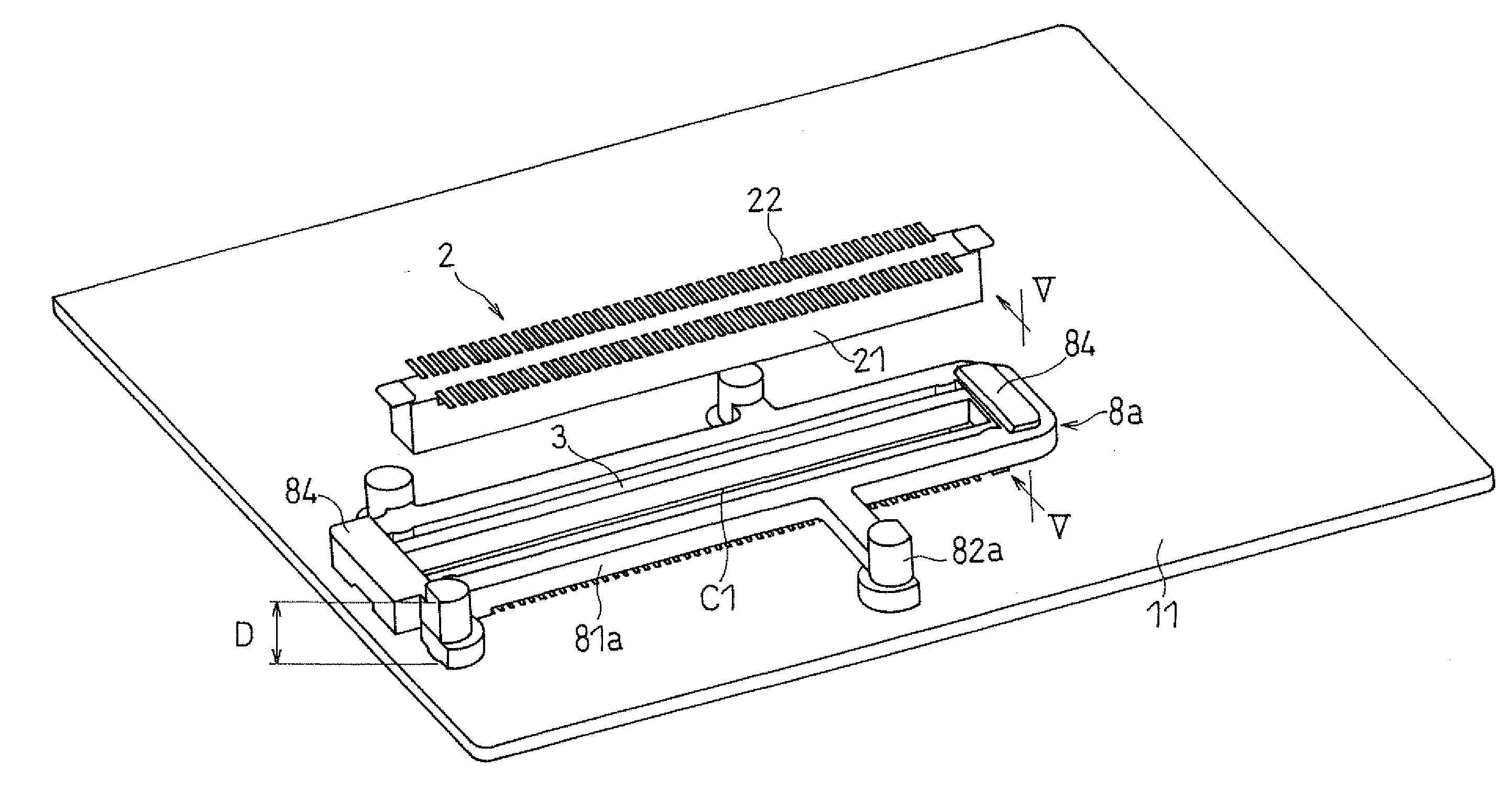
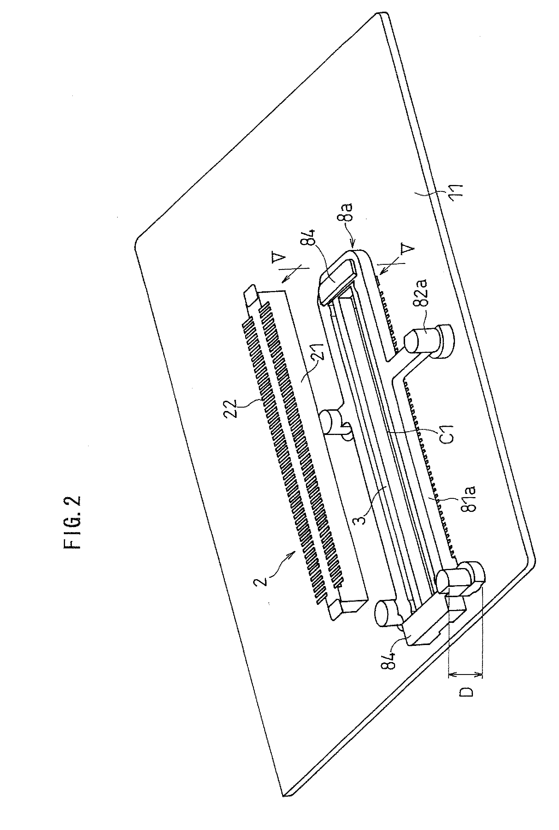
[0045]Referring to FIGS. 1, 2, 3, 4, 5, 6, 7, 8, and 9, an electronic device according to a first embodiment of the present invention will be described by taking a digital camera as an example. In the present embodiment, a connector reinforcement member 8a is provided around a female connector 3 in order to prevent the female connector 3 from being excessively distorted by an undesirable force.

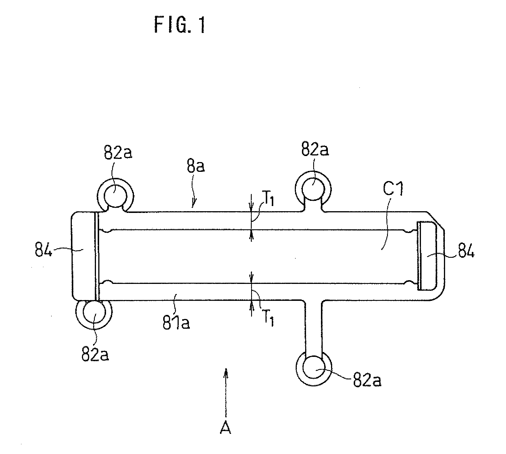
[0046]FIG. 1 illustrates a plan view of the connector reinforcement member 8a. The connector reinforcement member 8a is normally made up of a resin material, and includes a frame portion 81a, spacers 82a, and guiding portions 84. The frame portion 81a is formed of a rod-like material into an elongated rectangular ring shape with a central hollow portion Cl in which to fit a housing 31 of the female connector 3.

[0047]The hollow portion C1 is formed by prismatic portions, each having a rectangular cross section defined by, for example, width T1×length T2 (FIG. 3), and the shape of the hollow por...

second embodiment

[0069]A connector reinforcement member included in an electronic device according to a second embodiment of the present invention will be described with reference to FIGS. 10 and 11. As described above, the connector reinforcement member 8a in the first embodiment is disposed so as to surround the female connector 3 and stay out of contact with the circuit board 11. On the other hand, a reinforcement member 8b in the present embodiment is disposed so as to surround a portion of the female connector 3, and secured to the circuit board 11.

[0070]Specifically, the connector reinforcement member 8a takes advantage of a constriction force (i.e., tension) of the frame portion 81a to prevent the housing 31 of the female connector 3 from being excessively distorted, while the reinforcement member 8b takes advantage of a reactive force of the circuit board 11 to prevent the housing 31 of the female connector 3 from being distorted. FIG. 10 illustrates a plan view of the connector reinforcemen...

third embodiment

[0078]A connector reinforcement member provided in an electronic device according to a third embodiment of the present invention will be described with reference to FIG. 12. A connector reinforcement member 8c in the present embodiment differs from the connector reinforcement member 8a in the first embodiment, in that the spacers 82a are replaced by spacers 82b as included in the connector reinforcement member 8b in the second embodiment. Specifically, the snap portion 87 and the slope portion 88 are provided at the bottom of each spacer 82a as included in the connector reinforcement member 8a.

[0079]Therefore, the connector reinforcement member 8c has both the function of the connector reinforcement member 8a surrounding the female connector 3, and the function of the reinforcement member 8b secured to the circuit board 11. Thus, it is possible to achieve an advantageous effect of preventing any damage to the connectors as compared to those achieved in the first and second embodime...


PUM


Abstract

An electronic device has provided therein at least a first circuit board 11 and a second circuit board 12, which are electrically connected together, the device including: a female connector 3 secured to the first circuit board 11 and having an opening; a male connector 2 secured to the second circuit board 12 and inserted into the opening; and a connector reinforcement member 8 provided close to the female connector 3, wherein the connector reinforcement member 8 is brought into contact with the female connector 3, which is about to be distorted by an external force, thereby suppressing distortion of the female connector 3.

Description

FIELD OF THE INVENTION[0001]The present invention relates to electronic devices, and more particularly to an electronic device with a connector for connecting a plurality of circuit boards together.BACKGROUND OF THE INVENTION[0002]Recent years have seen a number of proposals of digital cameras provided with an imaging element, which is a kind of electronic circuit, such as a CCD (charge-coupled device), or a CMOS (complementary metal-oxide semiconductor). The digital camera is configured to receive an optical image by an imaging element, and output it after conversion to an electrical image signal, so that image information is recorded to a memory device, such as a built-in memory device or a removable memory card.[0003]In recent years, such digital cameras have increasingly tended to have an imaging element with a higher pixel count and a more compact size. As the pixel count of the imaging element becomes higher, the file size of the image information to be outputted is increased,...

Claims


Application Information

Patent Timeline
IPC IPC(8): H01R12/14H01R12/51H01R12/72
CPCH01R13/53H01R12/716H01R12/52
Inventor SAIKI, JUN
Owner PANASONIC CORP
Why Eureka
Eureka Blog
Learn More