
Method for controlling parallel kinematic mechanism machine and control apparatus therefor

a technology of kinematic mechanism machine and control apparatus, which is applied in the direction of programmed control, manipulators, instruments, etc., can solve the problems of inability to obtain high-accuracy compensation, shafts that blend together and increase according to the conditions, and the effect of reducing the effect of rotational resistance deformation errors

Inactive Publication Date: 2008-06-12
OKUMA CORP
View PDF6 Cites 19 Cited by
  • Summary
  • Abstract
  • Description
  • Claims
  • Application Information

AI Technical Summary

Benefits of technology

[0034]According to the present invention, the present invention achieves an effect to provide a control method and control apparatus of a parallel kinematic mechanism machine which decides the end-effector position and posture still more accurately by performing compensation selectively taking into account of effects of rotational resistance for all passive shafts and by performing compensation that purely extracts only effects of rotational resistance by building up a model independent of effects of inertia, gravity, or the like.
[0035]In addition, according to the present invention, deformation errors by rotational resistance of the first universal joint and / or the second universal joint are taken into account in the event of calculating the estimation of kinematic parameters related to calibration. Thus, effects of deformation errors of mechanical elements by rotational resistance can be eliminated and the estimation accuracy of kinematic parameters can be still more improved.

Problems solved by technology

However, since effects of the passive shafts which are not subjected are not considered, the error is increased by that much according to the conditions.
Thus, effects from the factors and effects of passive shafts blend together and error increase according to the conditions.
Moreover, even when compensation using measurement values of rotational resistance in passive shafts is performed, interference with the factors occurs and high-accuracy compensation is not allowed to be obtained.
Thus, the measurement conditions at the time of diagnosis are restricted according to the conditions of the parallel kinematic mechanism machine, and it is difficult to perform accurate diagnosis when the measurement conditions differ from the measurement conditions related to the normal-time measurement data.
Moreover, when detailed diagnosis targeted to specific struts or joints is performed, it is not clear under what measurement conditions, the normal-time measurement data should be obtained, and it is difficult to implement accurate diagnosis for specific struts or joints.
Moreover, although normal / abnormal status of the struts or joints can be determined by comparing data with the normal-time data, it is difficult to specify abnormal joints or struts.

Method used


Image

  • Method for controlling parallel kinematic mechanism machine and control apparatus therefor
  • Method for controlling parallel kinematic mechanism machine and control apparatus therefor
  • Method for controlling parallel kinematic mechanism machine and control apparatus therefor

Examples


Embodiment Construction

[0059]Referring to drawings, a parallel kinematic mechanism machine of embodiments according to the present invention will be described hereinafter.

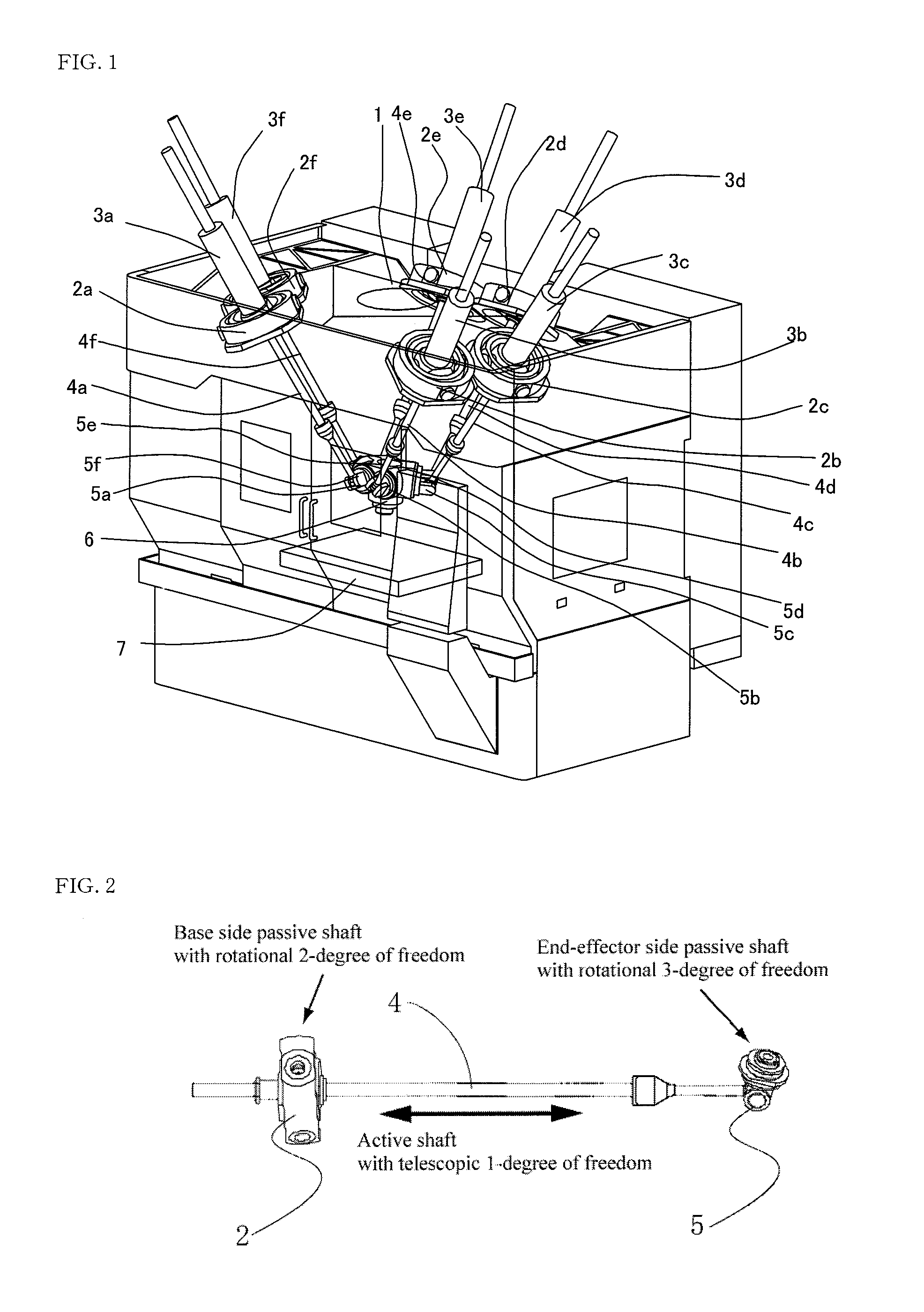
[0060]FIG. 1 is an explanatory view of a Stewart platform type parallel kinematic mechanism machine with six degrees of freedom, and this parallel kinematic mechanism machine includes a frame 1 as a base fixed to a floor, six first universal joints 2a through 2f fixed to the frame 1, servo motors 3a through 3f as actuators connected to each of first universal joints 2a through 2f, and ball screws 4a through 4f as struts driven by each of the servo motors 3a through 3f, second universal joints 5a through 5f connected to the bottom end of each of the ball screws 4a though 4f, one end-effector 6 having the second universal joints 5a through 5f, and a table 7 fixed to the frame 1 at the opposite location to the end-effector 6.

[0061]The end-effector 6 includes a cutting tool mounting section and cutting tool rotating mechanism on the bottom s...


PUM

PropertyMeasurementUnit
degrees of freedomaaaaaaaaaa
degree of freedomaaaaaaaaaa

Abstract

First of all, in a first step S1, each actuator command value for position command value and posture command value of an end-effector is determined. Next, in a second step S2, rotational resistance values of a first and a second universal joints are obtained, and in a third step S3, the force and the moment exerted to each of the second universal joints are computed using this, and in a fourth step S4, the resultant force and the resultant moment exerted to the end-effector are determined from these. Then, in the fifth step, the elastic deformation amount of a mechanism is computed using these, and a compensation amount of the actuator command value is computed using these values. And then, in the sixth step, the actuator command values determined in the first step are updated with the compensation amount determined in the fifth step taken into account.

Description

[0001]This application is a Continuing Application of U.S. patent application Ser. No. 11 / 779,455, having a filing date of Jul. 18, 2007, and claims the benefit under 35 USC §119(a)-(d) of Japanese Patent Application Number 2006-216478 filed Aug. 9, 2006, the entireties of which are incorporated by reference.BACKGROUND OF THE INVENTION[0002]1. Field of the Invention[0003]The present invention relates to a method for controlling a parallel kinematic mechanism machine in which an end-effector, which is connected with a plurality of struts driven by actuators via joints, is moved by the struts, and to an apparatus for implementing the method.[0004]2. Description of the Related Art[0005]As a conventional method for controlling a parallel kinemtic mechanism machine, a method described in the Japanese Patent Application Laid-Open No. 2006-11752 is known. In this method, in a parallel kinematic mechanism machine, in order to obtain cutting resistance at the time of machining, in addition t...

Claims


Application Information

Patent Timeline
Patent Type & Authority Applications(United States)
IPC IPC(8): B25J9/16G05B19/00G05B19/408
CPCB25J9/1623G05B2219/37343Y10T409/307672Y10T409/309576G05B2219/39186B25J9/1641
Inventor UENO, HIROSHIMATSUSHITA, TETSUYA
Owner OKUMA CORP
Learn More