Low power method of monitoring and of responsively initiating higher powered intelligent response to detected change of condition

a technology of intelligent response and detection, applied in the direction of electric variable regulation, process and machine control, instruments, etc., can solve the problems of clocking frequency, clocking logic or the like's equivalent, slow response speed, etc., to achieve faster response, less power, and faster response speed

Inactive Publication Date: 2006-08-10
EXAR CORP
View PDF8 Cites 34 Cited by
  • Summary
  • Abstract
  • Description
  • Claims
  • Application Information

AI Technical Summary

Benefits of technology

[0016] One particular embodiment disclosed herein includes an asymmetrically responsive, Low-power Programmable Threshold-crossing Comparator (LPTC) that provides a relatively fast response to detection of a drop of a given, first voltage (received at an INN node) relative to a supplied threshold (the drop of INN relative to the threshold being one that indicates a loss of memory-sustaining charge for example). The LPTC provides a relatively slower response to detection of an opposed situation where the monitored first voltage increases above the threshold voltage level. The LPTC thus draws less power when responding to a changed condition in that opposed and uninteresting situation. In one embodiment, the LPTC includes a low-power digital-to-analog converter (DAC) that is programmable to supply an appropriate analog reference voltage (to an INP node of the LPTC). In one embodiment, the low-power DAC is calibratable while in-system so that an accurate decision can be made as to whether the monitored voltage (INN) is falling dangerously close to, or below a defined reference voltage value.

Problems solved by technology

On the other hand, it is understood that the speed at which clock-driven sequential CMOS logic or the like can respond to emergency situations tends to slow as its clocking frequency is slowed.
Thus, in situations where it is desirable to have both low power consumption and fast, logical response by a sequential logic means to exigent circumstances, these two characteristics of CMOS logic (or its equivalents) conflict with one another.
One situation that may call for rapid response is imminent loss of the minimum sleep voltage, VSLEEPmin, as applied to essential memory; this for example being caused by parasitic loss of charge in the system-preserving, minimal power supply means due to passage to time and / or other causes (i.e., temperature change).
One problem with such mostly-asleep systems is that upon awakening, the system may not have adequate knowledge of the state of its surroundings and that state could be rapidly deteriorating or otherwise changing.
On the other hand, if the main drive clock is left always on, how can the mostly asleep system keep its power draw low while asleep?
Such start up delays may be unacceptable in emergency wake-up situations such as described above.

Method used


Image

  • Low power method of monitoring and of responsively initiating higher powered intelligent response to detected change of condition
  • Low power method of monitoring and of responsively initiating higher powered intelligent response to detected change of condition
  • Low power method of monitoring and of responsively initiating higher powered intelligent response to detected change of condition

Examples


Embodiment Construction

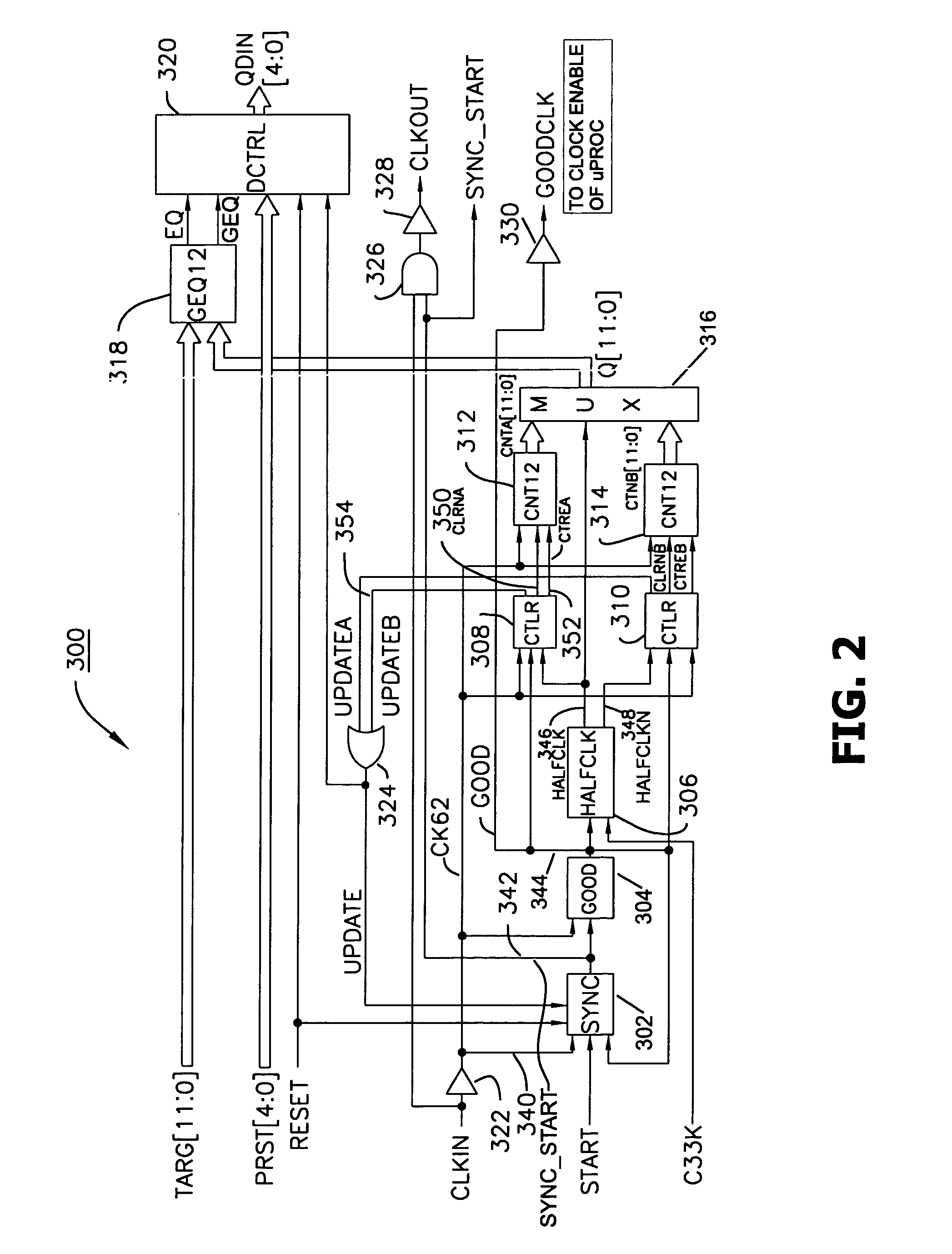
[0035] Referring to FIG. 13, a block diagram is provided of an illustrative system 1300 in accordance with the invention. While system 1300 sports a battery-powered, switched power supply (1301, 1305) having a low power sleep mode capability, the disclosure is not limited to just this illustrated application. The present teachings can find use in many other environments where it may be advantageous to provide one or both of a low power monitoring of vital system conditions and a higher powered, rapid intelligent or logical response to detected change of one or more of the monitored conditions.

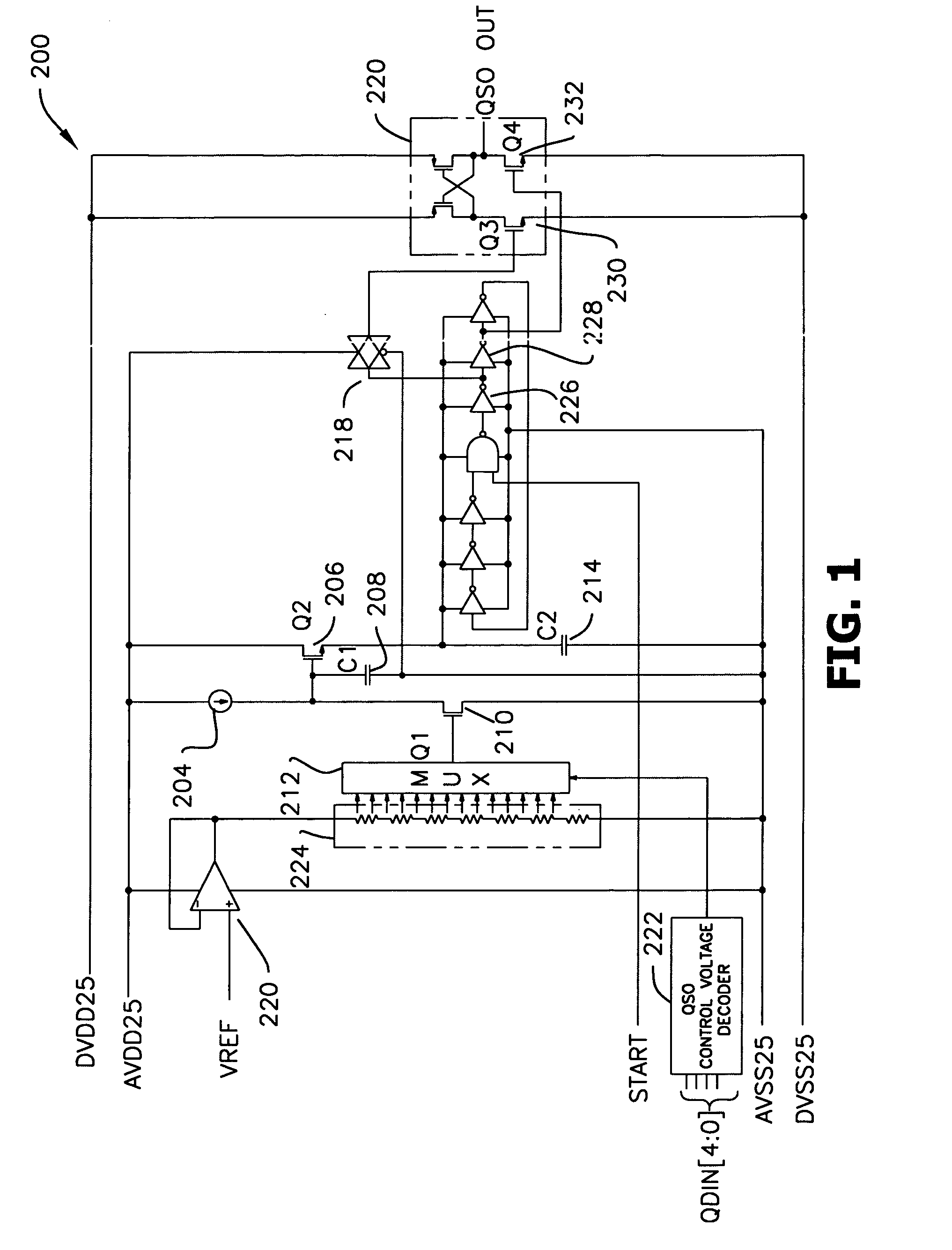
[0036] Three components of particular relevance in FIG. 13 are: (1) a plurality of low-power-consuming, condition monitors (1310a, 1310b, etc., only two shown) that respectively monitor vital conditions (e.g., voltages) within the system 1300; (2) at least one quick-start oscillator (QSO) 1330 that can have its oscillations quickly started (e.g., in much less than a millisecond) by any one of ...


PUM


Abstract

A synchronous control system includes a logic controller (e.g., microprocessor) which can be put into low power standby or sleep mode by shutting off its clock. A quick-start oscillator (QSO) remains shut off to conserve power when not needed, but awakens rapidly and supplies clock signals to the logic controller for quickly awakening the controller so the latter can to respond to exigent circumstances. One such circumstance can be the drop of a vital supply voltage below a predefined threshold. A low power comparator (LPTC) detects the drop and starts up the QSO which in turn awakens the controller. The controller determines what the reason for the awakening is, quickly responds to the exigent circumstance and then turns the QSO off to thereby conserve power and put itself (QSO) back to sleep. Disclosures are provided for the QSO and a first calibration subsystem used to maintain QSO output frequency within a desired range. Disclosures are provided for the LPTC and a second calibration subsystem used to set its trigger threshold. Disclosure of a novel DAC within the LPTC is also provided.

Description

CLAIM OF BENEFIT [0001] The present application is a continuation-in-part (CIP) of below cited, Ser. No. 60 / 641,889 and claims benefit thereof to the extent permitted by law. CROSS REFERENCE TO CO-OWNED APPLICATIONS [0002] The following copending U.S. provisional or regular patent applications are owned by the owner of the present application, and their disclosures are incorporated herein by reference: [0003] (A) Ser. No. 60 / 641,889 [Attorney Docket No. M-15769-V1] filed Jan. 5, 2005 by Kent Kernahan et al and originally entitled, LOW VOLTAGE DETECTOR AND QUICK START OSCILLATOR FOR LOW QUIESCENT POWER OPERATION; [0004] (B) Ser. No. 11 / 030,688 [Attorney Docket No. M-15428] filed Jan. 5, 2005 by Milton D. Ribeiro and Kent Kernahan and originally entitled, Switching Power Converter Employing Pulse Frequency Modulation Control; CROSS REFERENCE TO PATENTS [0005] The disclosures of the following U.S. patents are incorporated herein by reference: [0006] (A) U.S. Pat. No. 6,825,644 issued N...

Claims


Application Information

Patent Timeline
Patent Type & Authority Applications(United States)
IPC IPC(8): G05F5/00
CPCG06F1/3203G06F1/3237Y02B60/1282Y02B60/1217Y02B60/1221G06F1/3287Y02D10/00G11C5/14
Inventor KERNAHAN, KENTTHOMAS, JOHN CARLLAMBERT, CRAIG NORMAN
Owner EXAR CORP
Why Eureka
Try Eureka