Rotary wing aircraft proximity warning system with a geographically based avoidance system

a proximity warning and aircraft technology, applied in the field of avoidance systems, can solve the problems of limiting the common introduction of these systems into aircraft, affecting the accuracy of the proximity warning system, so as to prevent interference with delicate ground based instruments

Active Publication Date: 2008-06-12
SIKORSKY AIRCRAFT CORP
View PDF16 Cites 20 Cited by
  • Summary
  • Abstract
  • Description
  • Claims
  • Application Information

AI Technical Summary

Benefits of technology

The present invention is a system that prevents interference with sensitive ground-based instruments. It is designed to be affordable and effective.

Problems solved by technology

The technical problem addressed in this patent is the need for an affordable avoidance system that can prevent interference with sensitive ground-based instruments and geographic areas, while minimizing the likelihood of contact with obstacles such as telephone lines and power plants. Current systems are expensive and require specialized emitters, which limit their common use in aircraft.

Method used


Image

  • Rotary wing aircraft proximity warning system with a geographically based avoidance system
  • Rotary wing aircraft proximity warning system with a geographically based avoidance system
  • Rotary wing aircraft proximity warning system with a geographically based avoidance system

Examples


Embodiment Construction

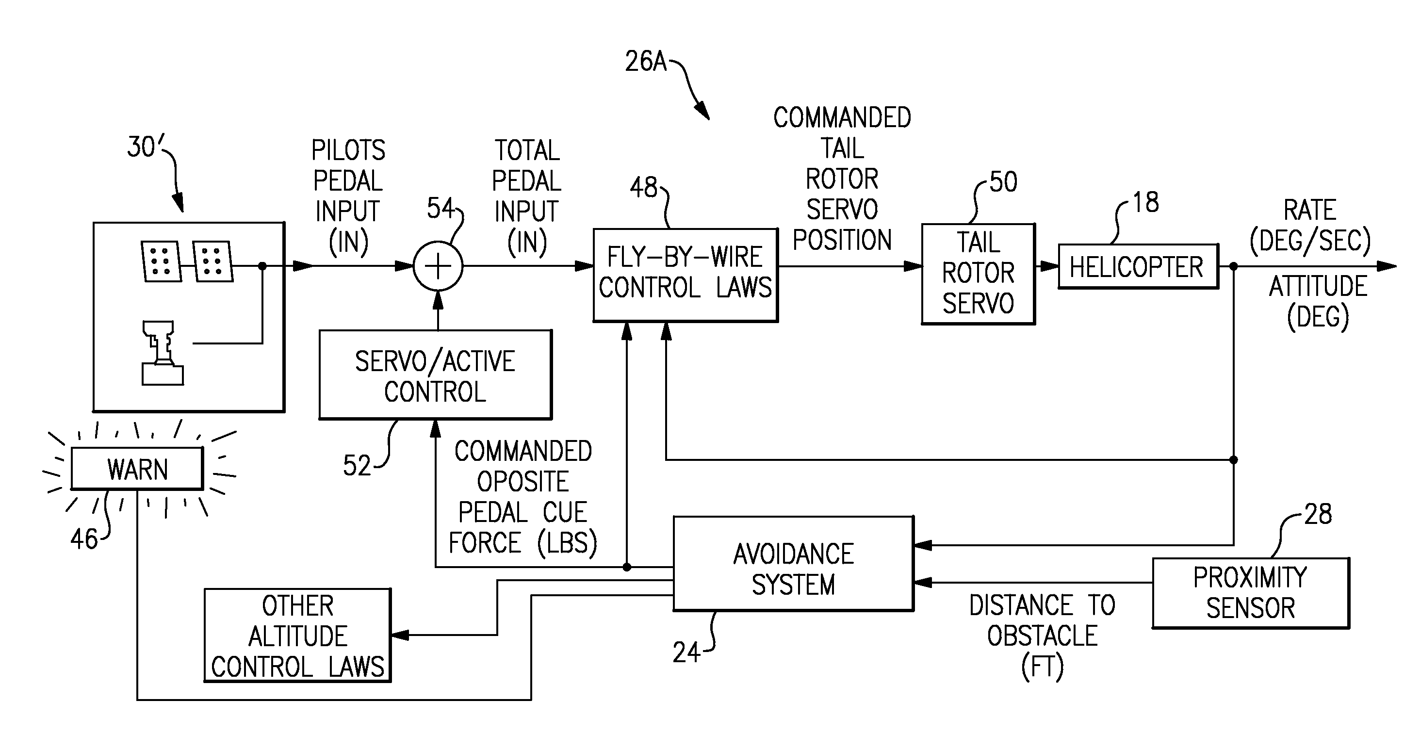
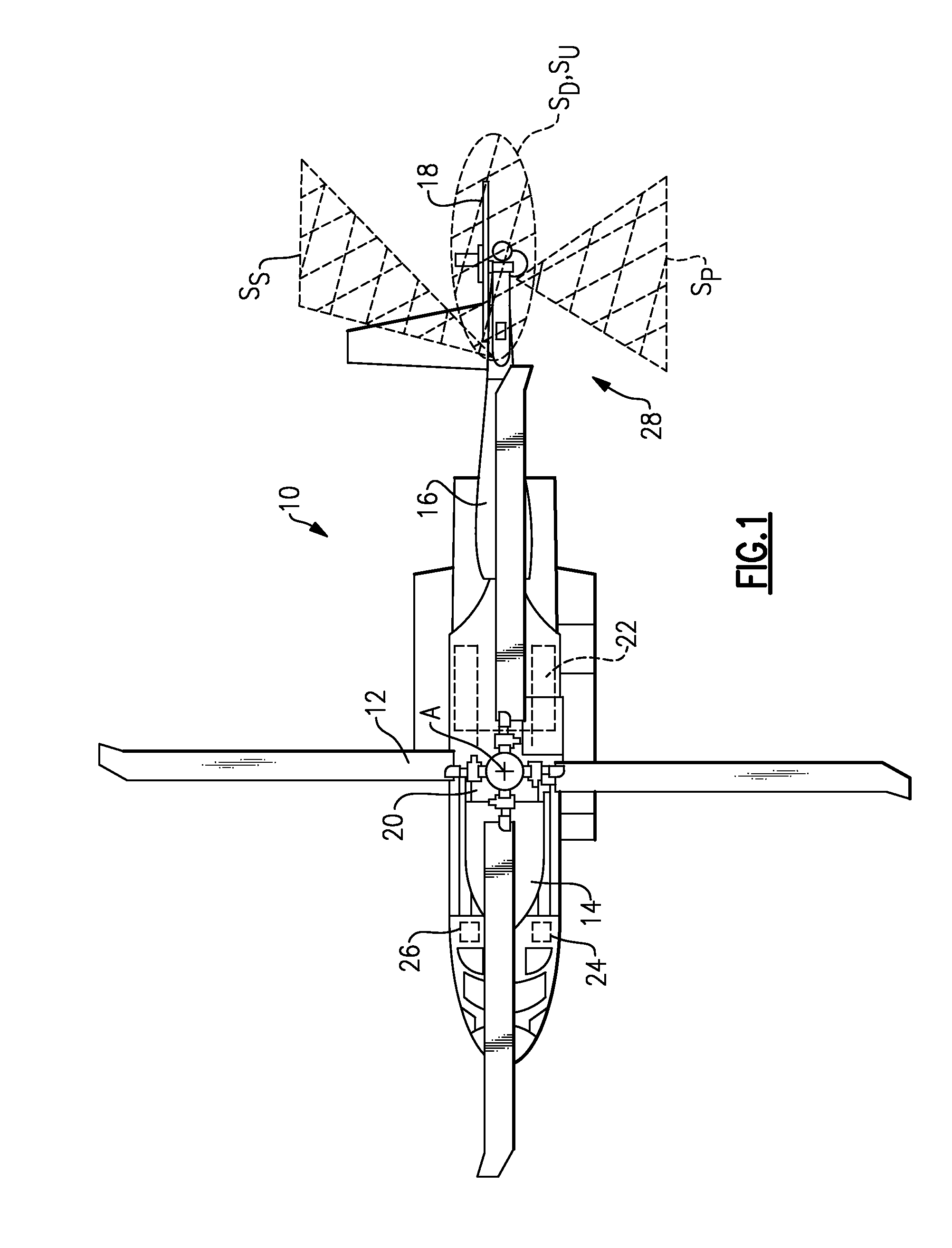
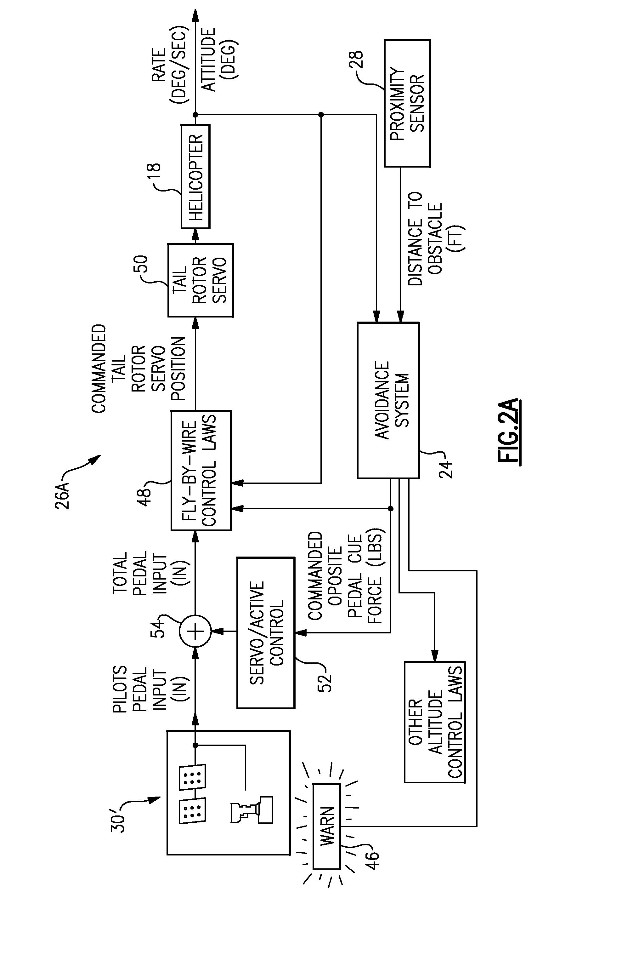
[0020]As schematically illustrated in FIG. 1, a rotary-wing aircraft 10 generally includes a fuselage 14, a main rotor system 12 and an extending tail 16 which may include a tail rotor system such as an anti-torque tail rotor 18, a rotor propulsion system or the like. The main rotor system 12 is driven about an axis of rotor rotation A through a transmission (illustrated schematically at 20) by one or more engines 22. Although a particular helicopter configuration is illustrated and described in the disclosed embodiment, other configurations and / or machines, such as jet aircraft, turbo-props, tilt-rotor and tilt-wing aircraft, will also benefit from the present invention.

[0021]The aircraft 10 includes an aircraft flight control system 26 having an avoidance system 24 integrated therewith. The avoidance system 24 preferably includes a proximity sensor suite 28 which may, for example only, be located within the extending tail 16 but may alternatively or additionally be located anywher...


PUM


Abstract

A safety enhancement warning system includes an avoidance system which communicates with a multiple of geographical positional systems. A geographic algorithm of the avoidance system utilizes a recursive algorithmic to determine if the aircraft will enter a sensitive area. If the aircraft distance to a sensitive area decreases below a predefined minimum threshold, then an audible and/or visual warning is issued. For certain sensitive areas, aircraft RF emissions are silenced or reduced in power when the predetermined minimum threshold breaches the sensitive area. The use of the avoidance system enables usage of relatively inexpensive UWB radar for the proximity sensor suite to assure avoidance of interference with particular delicate instruments and thereby meet regulations such as those propagated by the FCC.

Description


Claims


Application Information

Patent Timeline
Owner SIKORSKY AIRCRAFT CORP
Why Eureka
Try Eureka