Fire damper latching apparatus

a technology of latching apparatus and damper, which is applied in the direction of lighting and heating apparatus, wing accessories, heating types, etc., can solve the problems of awkward or difficult inspection of the apparatus, and the unsatisfactory condition of resetting the assembly in the condition of automatic closing of the passag

Inactive Publication Date: 2008-06-19
GLOBE TECH CORP
View PDF24 Cites 10 Cited by
  • Summary
  • Abstract
  • Description
  • Claims
  • Application Information

AI Technical Summary

Benefits of technology

[0008]The retainer of each latch member is so configured as to pass through an opening in the latch keeper member and, once the latch member is in its latching condition, the retainer cooperates with the keeper to provide secure support for the fusible link assembly. However, m

Problems solved by technology

A typical air passage is relatively small in area and the location of a damper in such passage may be such that inspection of the apparatus is awkward or difficult.
In those cases in whi

Method used


Image

  • Fire damper latching apparatus
  • Fire damper latching apparatus
  • Fire damper latching apparatus

Examples


Embodiment Construction

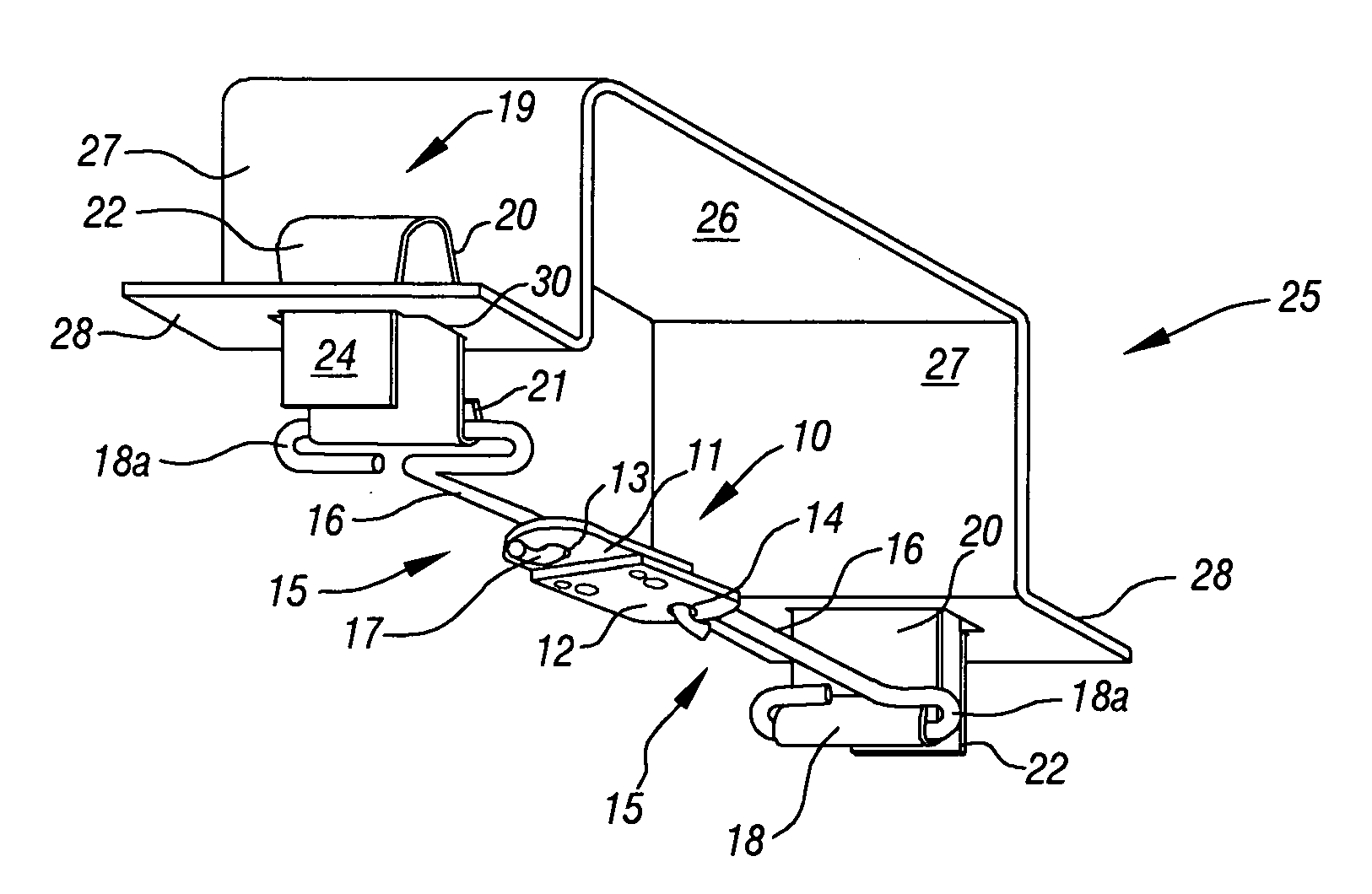
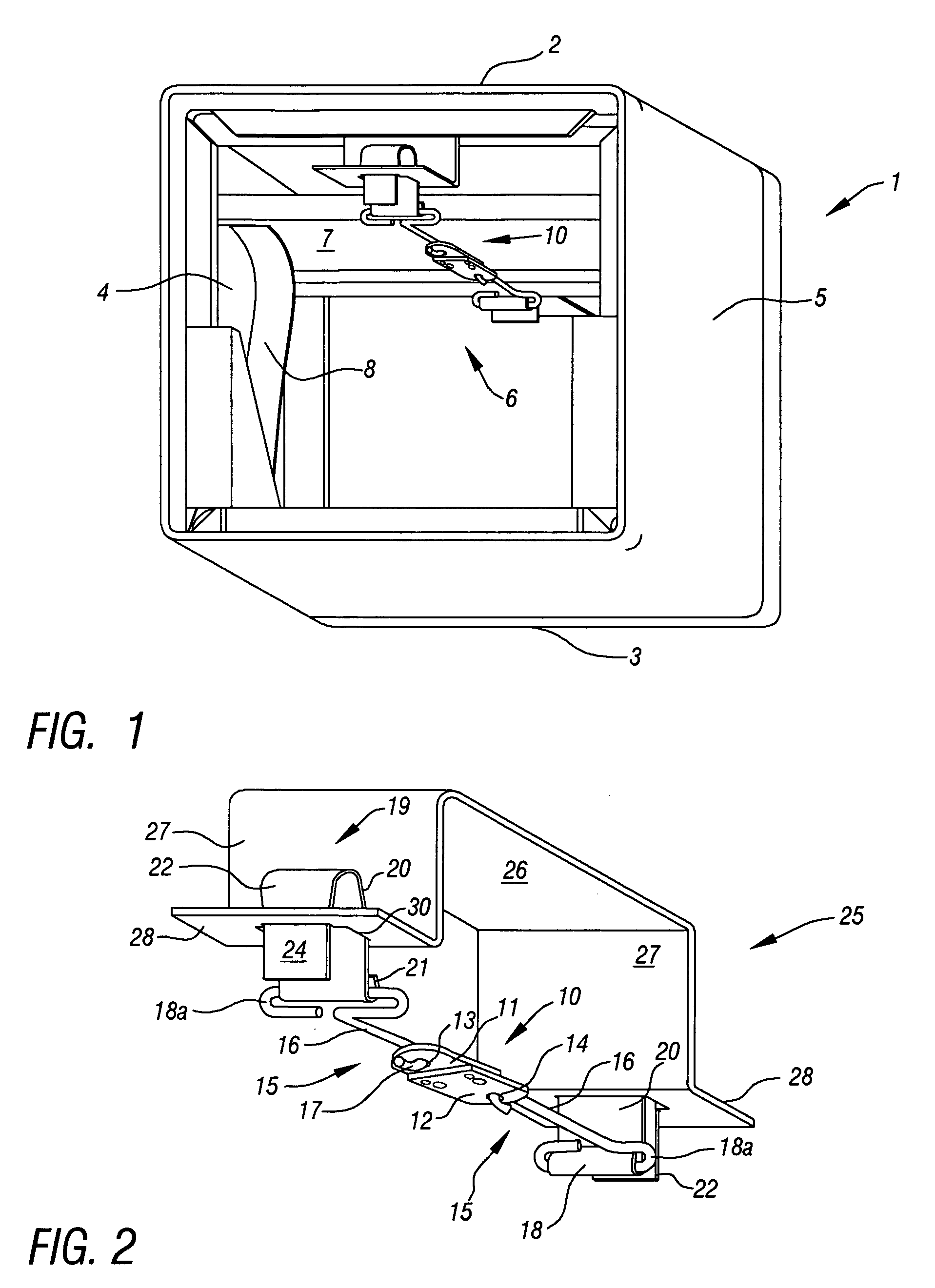
[0016]Apparatus constructed in accordance with the embodiment of the invention disclosed in FIGS. 1-4 is adapted for installation in a frame 1 having top and bottom walls 2 and 3, respectively, and opposed side walls 4 and 5. The frame 1 is of such size as to be accommodated in a conventional duct (not shown) forming a passage (of which the frame is a part) through which air may flow from a source (not shown) to one or more outlets (not shown) through which air may be discharged to one or more areas within a building.

[0017]Within the frame 1 is a damper assembly 6 comprising a plurality of leaves 7 pivotally coupled to one another in known manner. The uppermost leaf is secured to the inner surface of the top wall 2 and the leaves 7 are so arranged that they may move from retracted or nested passage-open condition, as shown in FIG. 1, to a passage-closed condition in which the leaves together form a partition extending between the top and bottom walls of the frame so as to block the ...


PUM


Abstract

Latching apparatus for use with a fire damper assembly wherein extendable and retractable damper leaves normally are maintained by a fusible linkage in a position enabling air to flow through a duct. The fusible linkage may be coupled to and uncoupled from a damper-supporting frame so as to facilitate testing of the damper assembly to ensure it is capable of automatically moving from its passage-open position to a passage-closed position in response to a predetermined rise in ambient temperature. The latching mechanism is operable simply by squeezing a spring retainer to enable it to pass into and out of latched engagement with a latch keeper.

Description

[0001]This invention relates to latching apparatus adapted for use in connection with a fire damper of the kind having leaves normally occupying a selected one of two positions, the latch apparatus being easily and quickly operable to enable the damper leaves to occupy either position.BACKGROUND OF THE INVENTION[0002]It is common practice to equip buildings with ducts forming passages through which air may flow from a source to a plurality of areas into which such air may be discharged. It also is common practice to install in such air passages one or more dampers each of which normally occupies a position in which air is enabled to flow through the passage to an outlet. However, in the event of an increase of ambient temperature to a predetermined level it is desirable that the damper be movable automatically from a position in which air may flow through the passage to an adjusted position in which the flow of air through such passage is blocked.[0003]In those instances in which am...

Claims


Application Information

Patent Timeline
IPC IPC(8): E05F15/20
CPCA62C2/242Y10T16/22F24F2011/0098F24F13/1426F24F11/35
Inventor GOATES, ELDON
Owner GLOBE TECH CORP
Why Eureka
Try Eureka