Self-moving tunnel support canopy

a tunnel and support technology, applied in the direction of shaft equipment, shaft lining, mining structures, etc., can solve the problems of poor support methods and devices, affecting the progress of construction, and the non-implementation of the self-moving function of the support device, so as to achieve safe and reliable, effective and convenient

Active Publication Date: 2015-03-26
LI XINBIN
View PDF1 Cites 32 Cited by
  • Summary
  • Abstract
  • Description
  • Claims
  • Application Information

AI Technical Summary

Benefits of technology

[0006]In view of the above raised defects in the prior art, embodiments of the present invention are directed to providing a self-moving, time and manpower-saving, and safe and reliable tunnel support canopy.
[0020]The technical solutions provided in the embodiments of the present disclosure achieve the following beneficial effects:
[0021]The support canopy according to the present invention is capable of moving by itself, which may support the arch top and two side walls under the weak wall rock, provides uninterrupted support force against the top portion and the two side walls, and timely supports the arch top which is exposed just upon blasting. In addition, the support canopy according to the present invention not only supports the arch top portion, but also supports the two side walls, achieving an effect of securely supporting the entire slip surface. With the support canopy, the supported arch tunnel is prevented from caving and collapse. The support canopy is time and manpower saving, and safe and reliable. In addition to retaining the current traditional tunnel excavation construction process “step method construction process”, the support canopy according to the present invention provides effective and convenient support and guarding for the wall rock on step-like top portion.

Problems solved by technology

However, due to restrictions of various conditions, during construction of a mountain tunnel, blasting construction and routine support method are mainly used.
During implementation of the present invention, the inventor has identified that the prior art has at least the following problem: Conventional support device and method are time and manpower consuming and achieve poor safety, thereby affecting the progress of the construction.
Incidents regarding safety are mainly due to these poor support methods and devices.
In addition, the self-moving function is not implemented for the support device.

Method used


Image

  • Self-moving tunnel support canopy
  • Self-moving tunnel support canopy
  • Self-moving tunnel support canopy

Examples


Embodiment Construction

[0051]To make the objectives, technical solutions, and advantages of the present invention clearer, embodiments of the present invention are described in detail below with reference to the accompanying drawings.

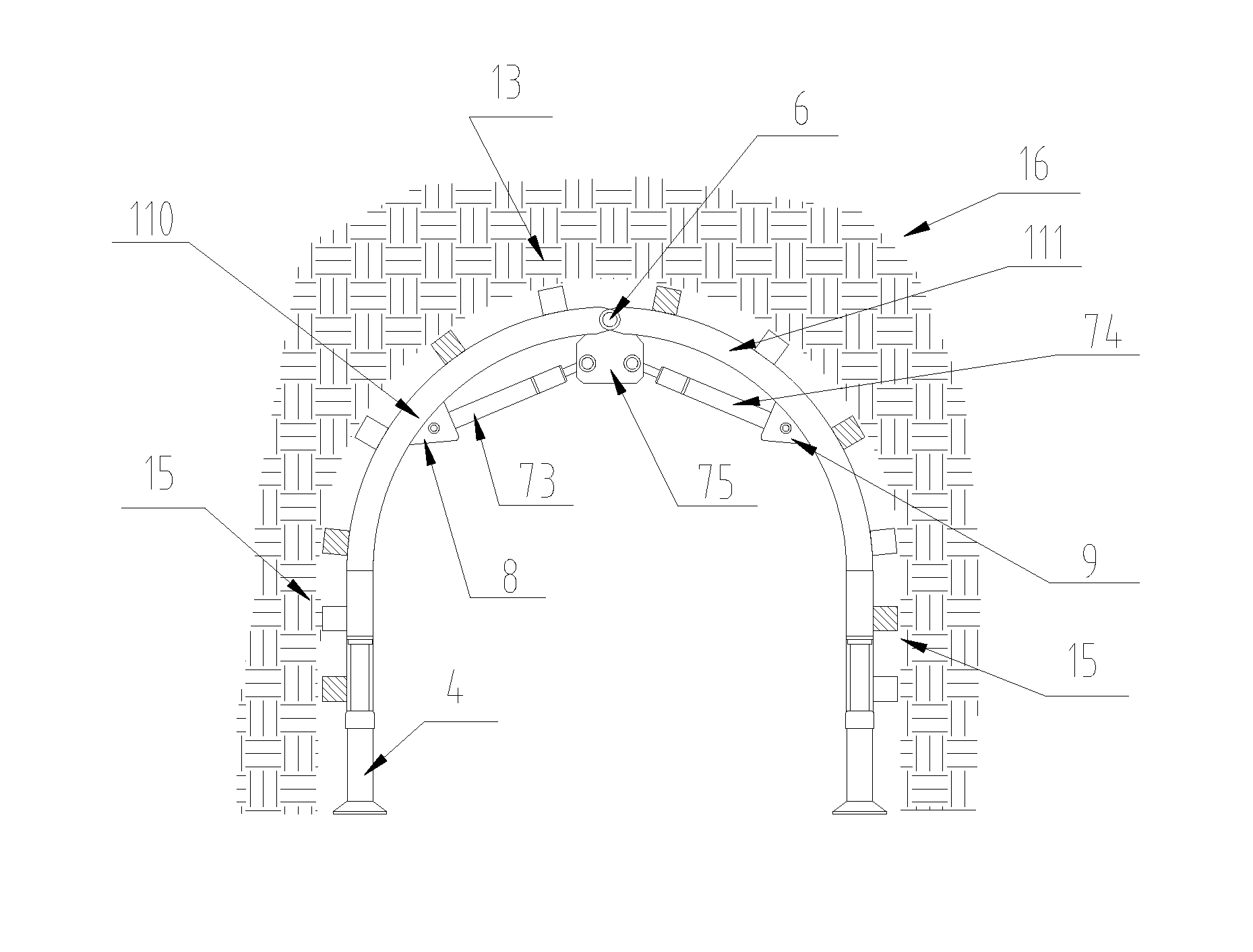
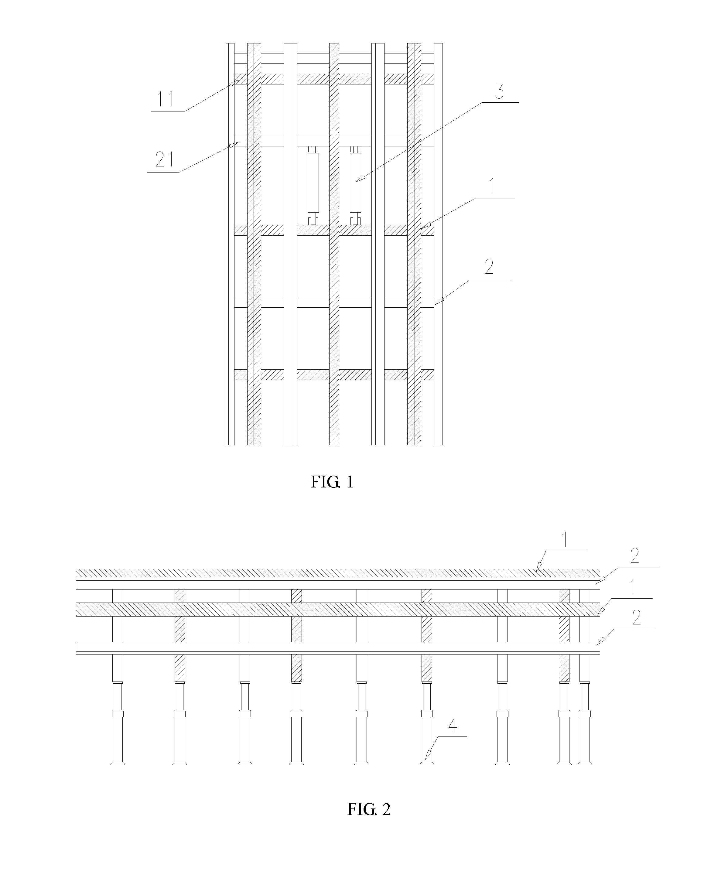
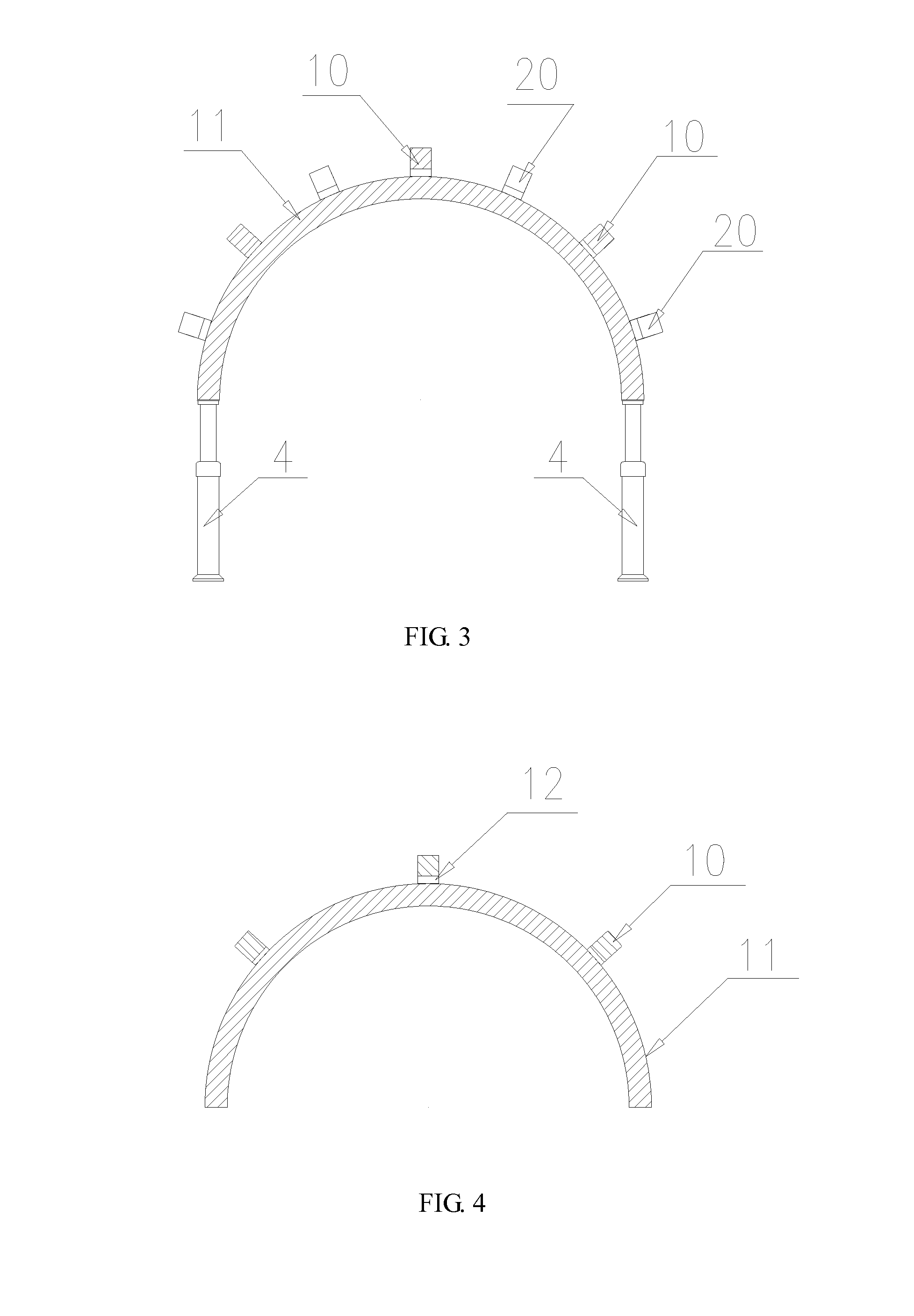
[0052]Referring to FIG. 1, FIG. 2, and FIG. 3, a self-moving tunnel support canopy comprises a front arch frame 1, a rear arch frame 2, a forward jack 3, and a support jack 4. The front arch frame 1 comprises more than three front longitudinal beams 10 and more than three front arch beams 11, wherein all the front longitudinal beams 10 are longitudinally disposed along arch upper surfaces of the front arch beams 11 at an equal interval, each of the front longitudinal beams 10 is coupled to all the front arch beams 11, a cushion block 12 is disposed at each of the joints of the front longitudinal beams 10 and the front arch beams 11 and is integrally fixed thereto, and the support jack 4 is disposed at a lower part of the front arch frame 1. The rear arch frame 2 comprises mor...


PUM


Abstract

A self-moving tunnel support canopy includes front arch frame, rear arch frame, forward jack, and support jack disposed under the front arch frame. The front arch frame has front arch beams and front longitudinal beams longitudinally disposed along arch upper surfaces of front arch beams and coupled to all the front arch beams. The rear arch frame has rear arch beams and rear longitudinal beams longitudinally disposed along arch upper surfaces of the rear arch beams and coupled to all the rear arch beams. The front longitudinal beams and the rear arch beams are spacedly disposed, and a spacing is configured between the front arch beam and a front-adjacent rear arch beam. One end is coupled to the front arch frame, and the other end of the forward jack is coupled to the rear arch frame. The front arch beam and the rear arch beam are both arch-shaped beams.

Description

CROSS-REFERENCE TO RELATED APPLICATION[0001]This application is the National Stage of International Application No. PCT / CN2012 / 077530, filed Jun. 26, 2012, which claims priority from Chinese Patent Application No. 201210127714.X, filed Apr. 26, 2012, which is incorporated herein by reference in its entirety.TECHNICAL FIELD[0002]The present invention relates to the fields of transportation, hydro engineering, and municipal tunnel excavation engineering, and in particular, to a self-moving tunnel support canopy.BACKGROUND[0003]In the prior art, a shield tunnelling machine is used to excavate a tunnel. However, due to restrictions of various conditions, during construction of a mountain tunnel, blasting construction and routine support method are mainly used.[0004]In known arch tunnels, the applied support device may be a steel arch frames, wherein the steel arch frame is formed by circular steel tubes or I-shaped steels that are bent to an arch shape, which is used to support wall roc...

Claims


Application Information

Patent Timeline
Patent Type & Authority Applications(United States)
IPC IPC(8): E21D9/06E21D11/40E21D23/04E21D15/14E21D23/08E21D23/03
CPCE21D9/0621E21D23/08E21D11/40E21D23/0427E21D15/14E21D23/03E21D11/28E21D11/30E21D23/0086E21D11/18E21D23/04E21D11/10E21D23/06E21D23/16
Inventor LI, XINBIN
Owner LI XINBIN
Why Eureka
Try Eureka