Check patentability & draft patents in minutes with Patsnap Eureka AI!

Modular interlocking graphics display panel

a technology of interlocking graphics and display panels, applied in the direction of identification means, signs, display means, etc., can solve the problems of creating many problems, requiring custom-built signs, and difficult lifting and moving of 10 foot by 8 foot signs to the place where they are needed

Inactive Publication Date: 2008-06-19
HITECH ELECTRONICS DISPLAY
View PDF17 Cites 64 Cited by
  • Summary
  • Abstract
  • Description
  • Claims
  • Application Information

AI Technical Summary

Problems solved by technology

This creates many issues.
For one, a 10 foot by 8 foot sign is difficult to lift and move to the place where it will be used.
Second, if someone else needs an 8 foot by 6 foot sign, a new sign needs to be custom built.
Third, if needs change such as a larger sign is needed, the existing sign becomes useless and a totally new sign must be deployed.
These issues are in addition to all of the issues common to graphic signs including protecting the sign from water, supporting the sign and connecting the sign to power and data.
Furthermore, due to access conditions, it is often difficult to service these signs once installed due to the availability of access to the front and back.
In other situations, it is impossible to get behind the sign and service must be performed from the front.
Although addressing some of the problems cited, these panels have irregular edges and require a frame to support the panels and provide power, even if only one panel is deployed.
There are no provisions in these panels to help reduce water buildup and damage.
These signs cannot be easily disassembled, serviced, moved and reassembled.

Method used


Image

  • Modular interlocking graphics display panel
  • Modular interlocking graphics display panel
  • Modular interlocking graphics display panel

Examples


Embodiment Construction

[0026]Reference will now be made in detail to the presently preferred embodiments of the invention, examples of which are illustrated in the accompanying drawings. Throughout the following detailed description, the same reference numerals refer to the same elements in all figures.

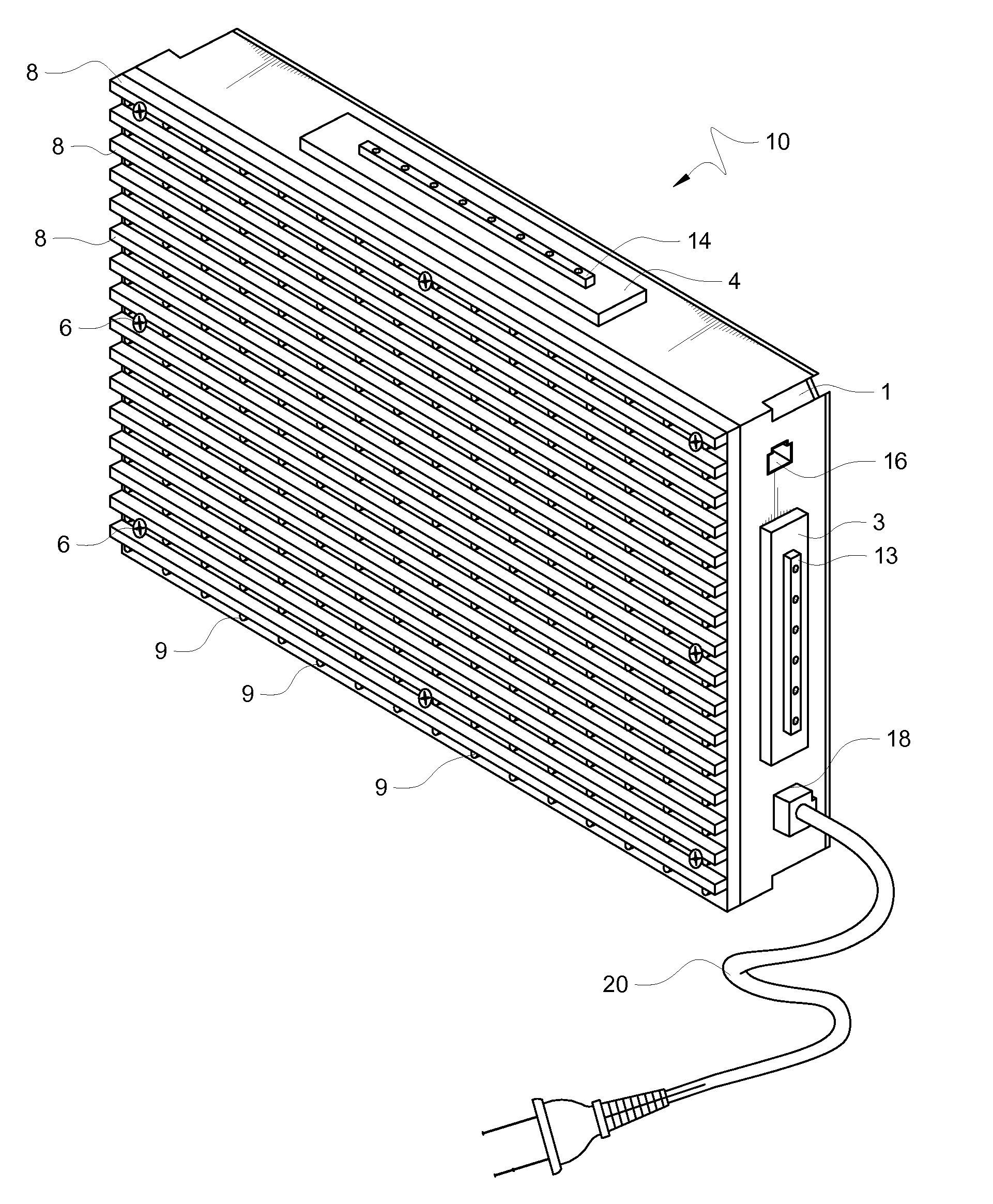
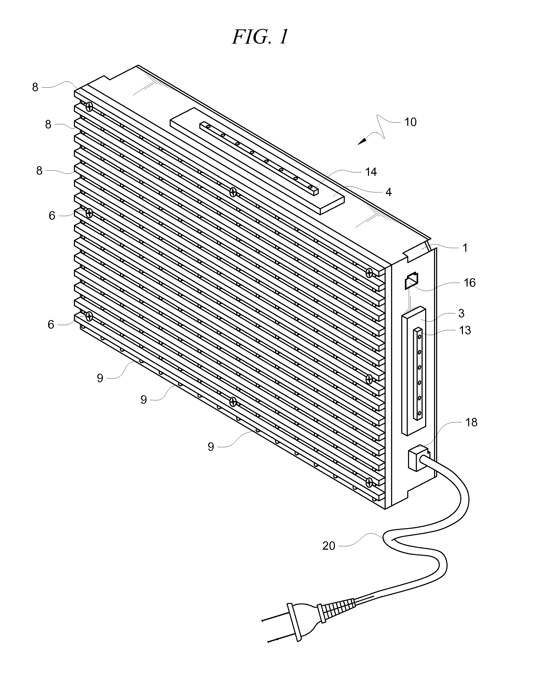
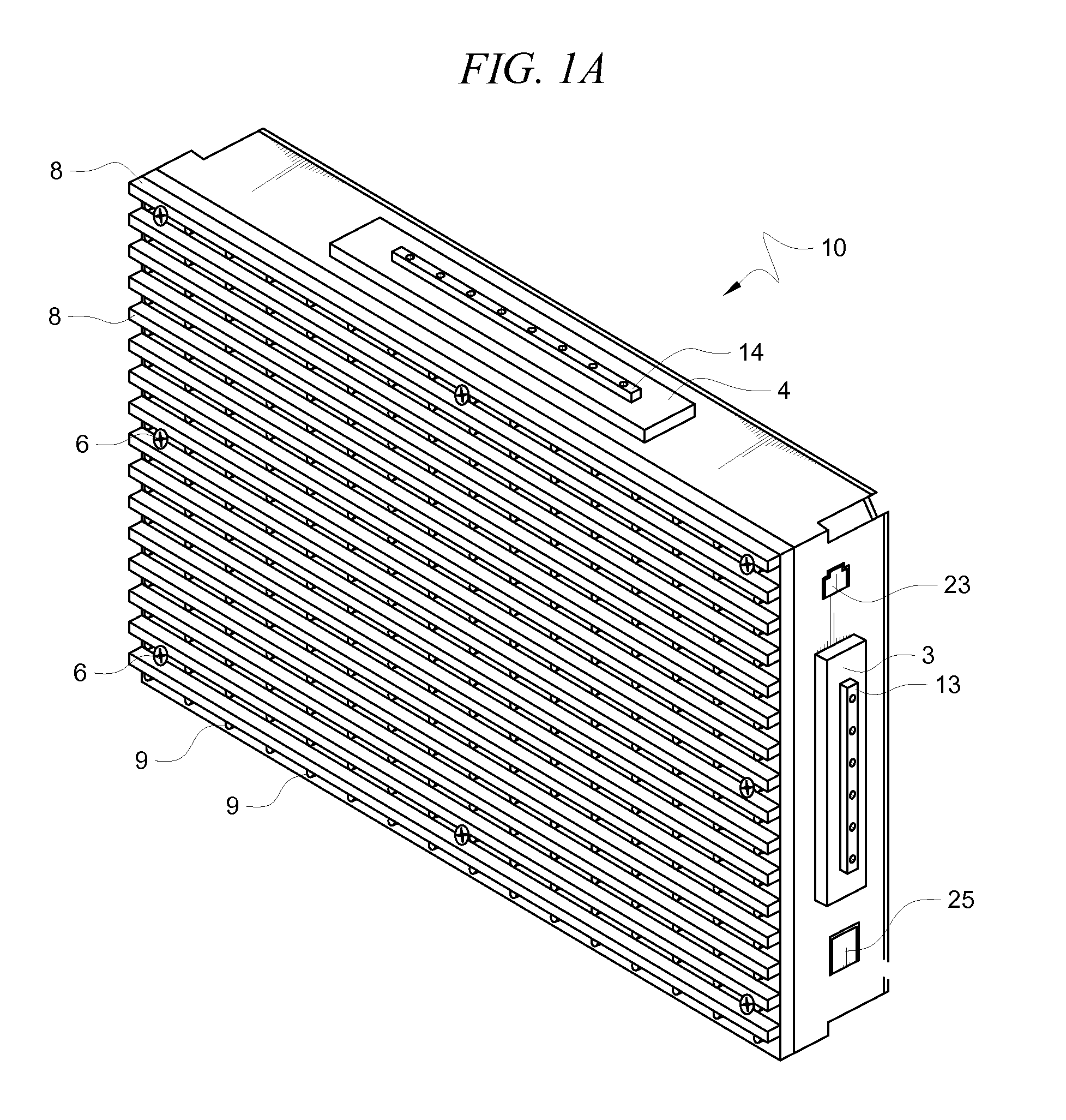
[0027]The modular graphic display panel 10 as shown in FIG. 1, FIGS. 1A, 2 and 3 has an exemplary power input 20 going through a side of its enclosure through a strain-relief 18 and into the modular graphic display panel 10 for powering the electronics of this display panel and any other display panel connected to it. A data input connector 16 is located on the same side of the display panel 10 for connecting to a driving computer system. In this example, an RJ-45 connector 16 is provided but the present invention is not limited to any particular connector, input style or interface. The connector can be any type of connector including RJ-11, RJ-45, D, Sub-D, etc, or the input signal can be directly wired pa...


PUM


Abstract

A modular graphics display panel includes an enclosure and an array of display elements mounted on a front surface of a bezel affixed to a front opening in the enclosure. Protrusions are made on two sides of the enclosure with a power / data connector mounted on the protrusions. Mating dimples are made on two opposite sides of the enclosure with mating power / data connectors mounted within the mating dimples. Corner keyholes are formed in each of the back corners of the enclosure for accepting locking keys.

Description

[0001]This application is related to U.S. application titled, “FRONT AND BACK SERVICABLE MODULAR INTERLOCKING GRAPHICS DISPLAY PANEL,” which was filed on even date herewith; attorney docket number 2236.1 and inventors Jeffrey C. Tomich and Shawn Kottwitz.BACKGROUND OF THE INVENTION[0002]1. Field of the Invention[0003]This invention relates to the field of electronic display signs and more particularly to interlocking graphics display panels that can be used alone or in conjunction with other similar panels to create a larger display.[0004]2. Description of the Related Art[0005]There are many products and related patents in the field of electronic signs. To date, most electronic signs are monolithic, in that if a 10 foot by 8 foot sign is needed, a 10 foot by 8 foot sign is designed and built. This creates many issues. For one, a 10 foot by 8 foot sign is difficult to lift and move to the place where it will be used. Second, if someone else needs an 8 foot by 6 foot sign, a new sign ...

Claims


Application Information

Patent Timeline
IPC IPC(8): G09F7/00
CPCG09F9/33
Inventor KOTTWITZ, SHAWN
Owner HITECH ELECTRONICS DISPLAY
Features
  • R&D
  • Intellectual Property
  • Life Sciences
  • Materials
  • Tech Scout
  • Unparalleled Data Quality
  • Higher Quality Content
  • 60% Fewer Hallucinations
Learn More