[0020]In a further aspect there is provided an ink supply system, further comprising a second ink line providing fluid communication between an outlet channel of said printhead and a return inlet of said ink reservoir, such that said ink supply system is a loop.Optionally, said return inlet comprises an ink filter for filtering returned ink.Optionally, a first pump is positioned in said first ink line upstream of said printhead.Optionally, said first pump is open and idle during printing, such that said pressure
regulator determines the
hydrostatic pressure of the ink in the printhead during printing.Optionally, a second pump is positioned in said second ink line downstream of said printhead.Optionally, said first and second pumps are independently configurable for priming, depriming, purging and printing operations.Optionally, said bubble outlet is dimensioned such that a hydrostatic pressure of ink in the chamber is at least 10 mm H2O less than
atmospheric pressure.Optionally, said bubble outlet has a
critical dimension controlling the
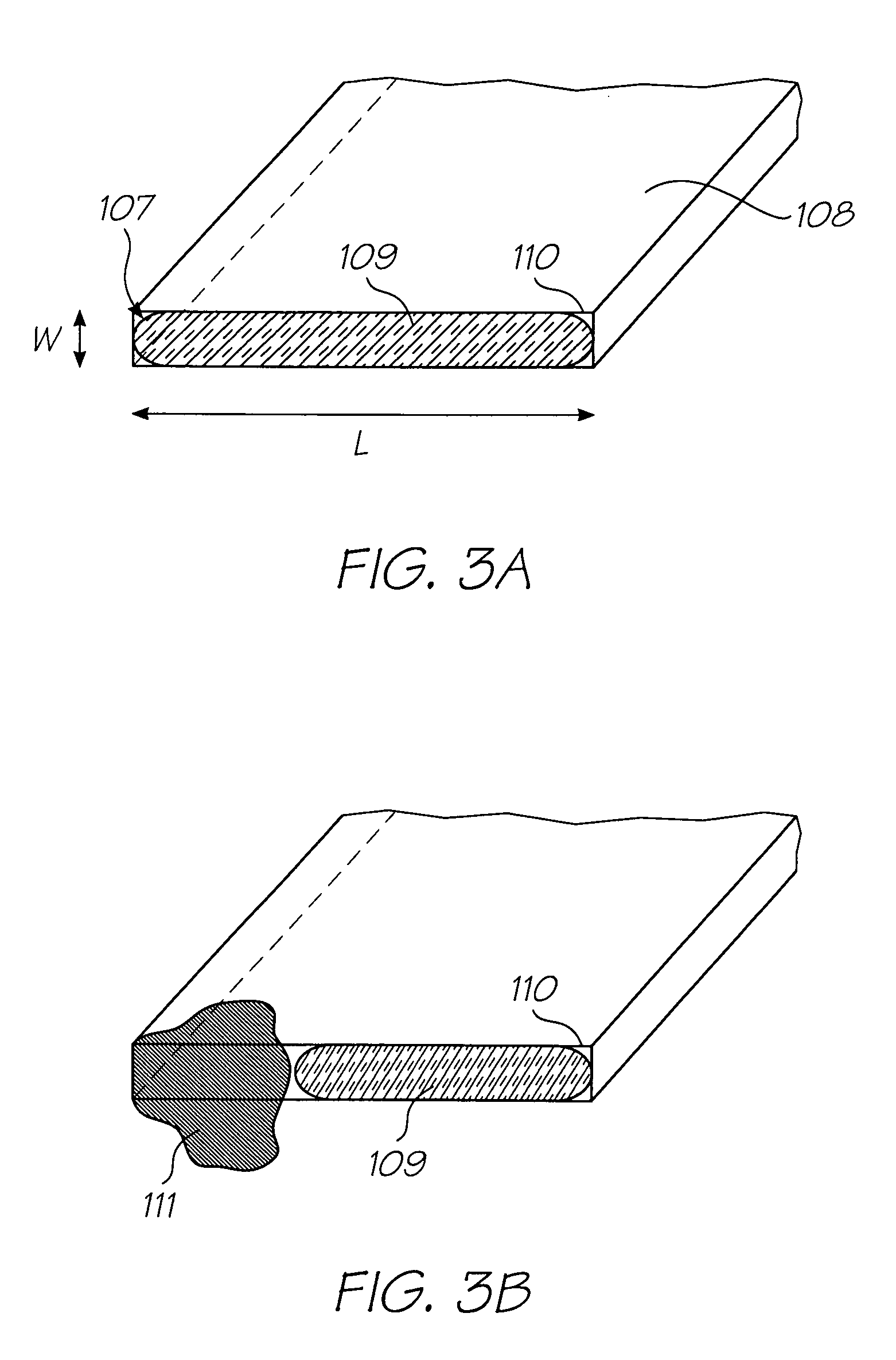
Laplace pressure of the air bubbles exiting the bubble outlet.Optionally, said bubble outlet is configured as a slot having a length dimension and a width dimension, such that said width dimension controls the
Laplace pressure of the air bubbles.Optionally, a width of said slot is less than 200 microns.Optionally, the bubble outlet is positioned for bubbling air bubbles into ink contained in the chamber, each
air bubble comprising an
air cavity trapped inside a body of ink.In a further aspect there is provided a pressure regulator, further comprising a pressure-release valve for releasing excess pressure in a headspace above ink in said chamber.Optionally, said
air channel is bent or tortuous for minimizing ink losses through the air inlet.Optionally, the bubble outlet is positioned for bubbling air bubbles into a headspace above ink contained in the chamber, each
air bubble comprising an air bubble trapped inside a film of ink.
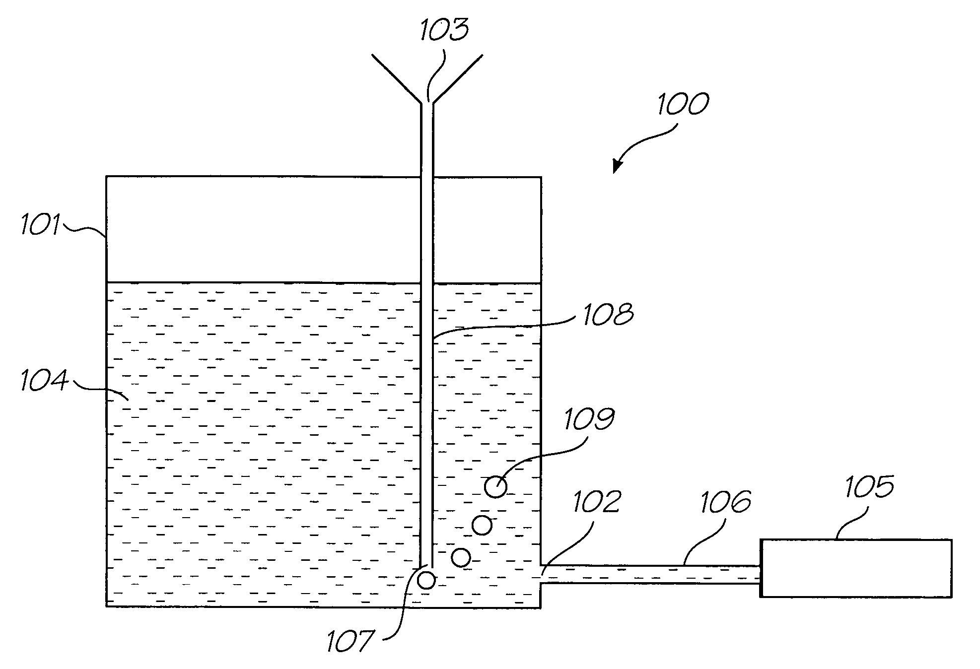
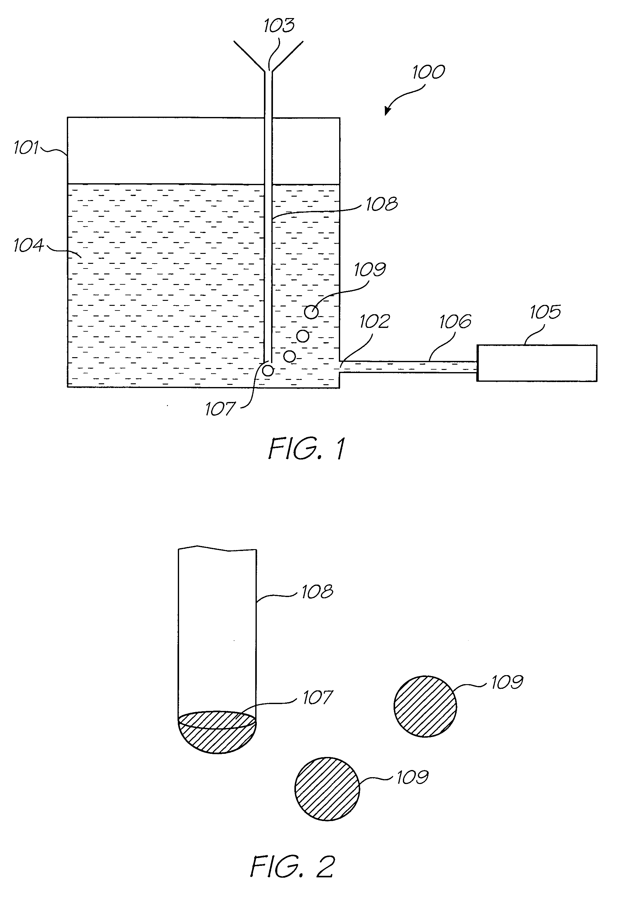
[0026]wherein said bubble outlet is dimensioned to control a Laplace pressure of air bubbles drawn into said ink as result of supplying ink to the printhead, thereby regulating a hydrostatic pressure of the ink.Optionally, said ink chamber is an ink reservoir for a printer.Optionally, said ink chamber has an ink inlet port for fluid communication with an ink reservoir.Optionally, said bubble outlet is dimensioned such that a hydrostatic pressure of ink in the chamber is at least 10 mm H2O less than
atmospheric pressure.Optionally, said bubble outlet is dimensioned such that a hydrostatic pressure of ink in the chamber is at least 100 mm H2O less than
atmospheric pressure.Optionally, said bubble outlet has a
critical dimension controlling the Laplace pressure of the air bubbles exiting the bubble outlet.Optionally, said bubble outlet is configured as a circular opening, such that a
radius of said circular opening controls the Laplace pressure of the air bubbles.Optionally, said bubble outlet is configured as a slot having a length dimension and a width dimension, such that said width dimension controls the Laplace pressure of the air bubbles.Optionally, a width of said slot is less than 200 microns.Optionally, each cross-sectional dimension of said
air channel is greater than the width of the slot, thereby minimizing flow resistance in the air channel.Optionally, said air channel is bent or tortuous for minimizing ink losses through the air inlet.Optionally, said air channel is dimensioned such that a maximum capillary volume of ink in said channel is less than about 0.1 mL.Optionally, one wall of said chamber comprises an air intake plate, said plate comprising the air inlet, the air channel and the bubble outlet.Optionally, said plate comprises a plurality of laminated
layers, said
layers cooperating to define the air inlet, the air channel and the bubble outlet.
[0045]wherein said bubble outlet is dimensioned to control a Laplace pressure of air bubbles drawn into said chamber as result of supplying ink to the printhead, thereby regulating a hydrostatic pressure of the ink.Optionally, said ink chamber is an ink reservoir for a printer.Optionally, said ink chamber has an ink inlet port for fluid communication with an ink reservoir.Optionally, said bubble outlet is dimensioned such that a hydrostatic pressure of ink in the chamber is at least 10 mm H2O less than atmospheric pressure.Optionally, said bubble outlet is dimensioned such that a hydrostatic pressure of ink in the chamber is at least 100 mm H2O less than atmospheric pressure.Optionally, said bubble outlet has a
critical dimension controlling the Laplace pressure of the air bubbles exiting the bubble outlet.Optionally, said bubble outlet is configured as a circular opening, such that a
radius of said circular opening controls the Laplace pressure of the air bubbles.Optionally, said bubble outlet is configured as a slot having a length dimension and a width dimension, such that said width dimension controls the Laplace pressure of the air bubbles.Optionally, a width of said slot is less than 200 microns.Optionally, the bubble outlet is positioned for bubbling air bubbles into ink contained in the chamber, each air bubble comprising an
air cavity trapped inside a body of ink.In a further aspect there is provided a pressure regulator, further comprising a
pressure release valve for releasing excess pressure in a headspace above ink in said chamber.Optionally, said air channel is bent or tortuous for minimizing ink losses through the air inlet.Optionally, the bubble outlet is positioned for bubbling air bubbles into a headspace above ink contained in the chamber, each air bubble comprising an air bubble trapped inside a film of ink.

