Gas burner

a burner and gas technology, applied in the field of gas burners, can solve the problems of complex production of components with holes through, and achieve the effect of reducing flow resistan

Inactive Publication Date: 2014-04-08
BSH BOSCH & SIEMENS HAUSGERAETE GMBH
View PDF16 Cites 7 Cited by
  • Summary
  • Abstract
  • Description
  • Claims
  • Application Information

AI Technical Summary

Benefits of technology

[0006]An object of the present invention is to provide a particularly simple gas burner, which ensures that the inner region of the burner is supplied with secondary air in a particularly reliable manner.
[0009]One important aspect of an exemplary embodiment of the invention is that the lower gas distribution chamber in the burner lower part is defined by a single component. This allows particularly simple production of the burner lower part, as it bounds the lower gas distribution chamber at the bottom and to the side. Using a single-part component means that no screwing or bonding processes are required to manufacture the burner lower part.
[0012]This means that the burner lower part is configured to be open at the top so that the entire lower gas distribution chamber is accessible vertically from above. This allows particularly simple production of the burner lower part, as no undercuts have to be made.
[0015]It is advantageous if the secondary air throughflow opening has a length of maximum 10 mm, preferably maximum 7 mm, particularly preferably maximum 5 mm, when viewed in the flow direction. The flow direction of the gas / air mixture through the secondary air throughflow opening is assumed to be vertical here. The length of the secondary air throughflow opening in the flow direction corresponds to the distance between the radial secondary air passage and the burner inner chamber. This dimension is determined by the material thickness of the component of the burner upper part in the region of the secondary air throughflow opening. The smallest possible extension of the secondary air throughflow opening in the flow direction is important to minimize the flow resistance for the secondary air. It is also expedient if each gas throughflow opening of the burner upper part corresponds to an outer region of the lower gas distribution chamber. The gas / air mixture thus flows by way of the outer regions of the lower gas distribution chamber through the gas throughflow openings into the burner upper part. The number of gas throughflow openings corresponds to the number of outer regions of the lower gas distribution chambers.

Problems solved by technology

This component with holes through it is complex to produce.

Method used


Image

  • Gas burner
  • Gas burner
  • Gas burner

Examples


Embodiment Construction

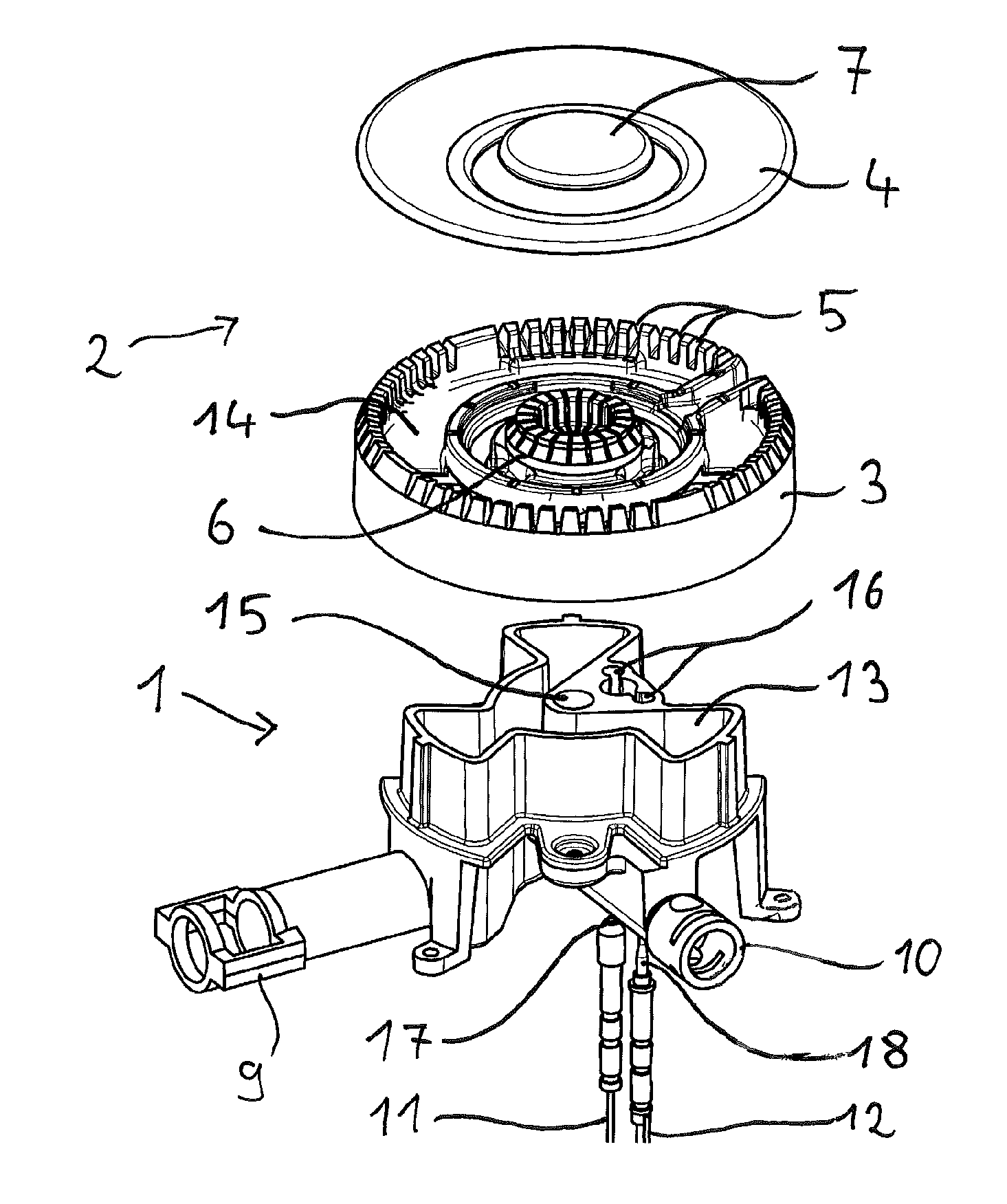
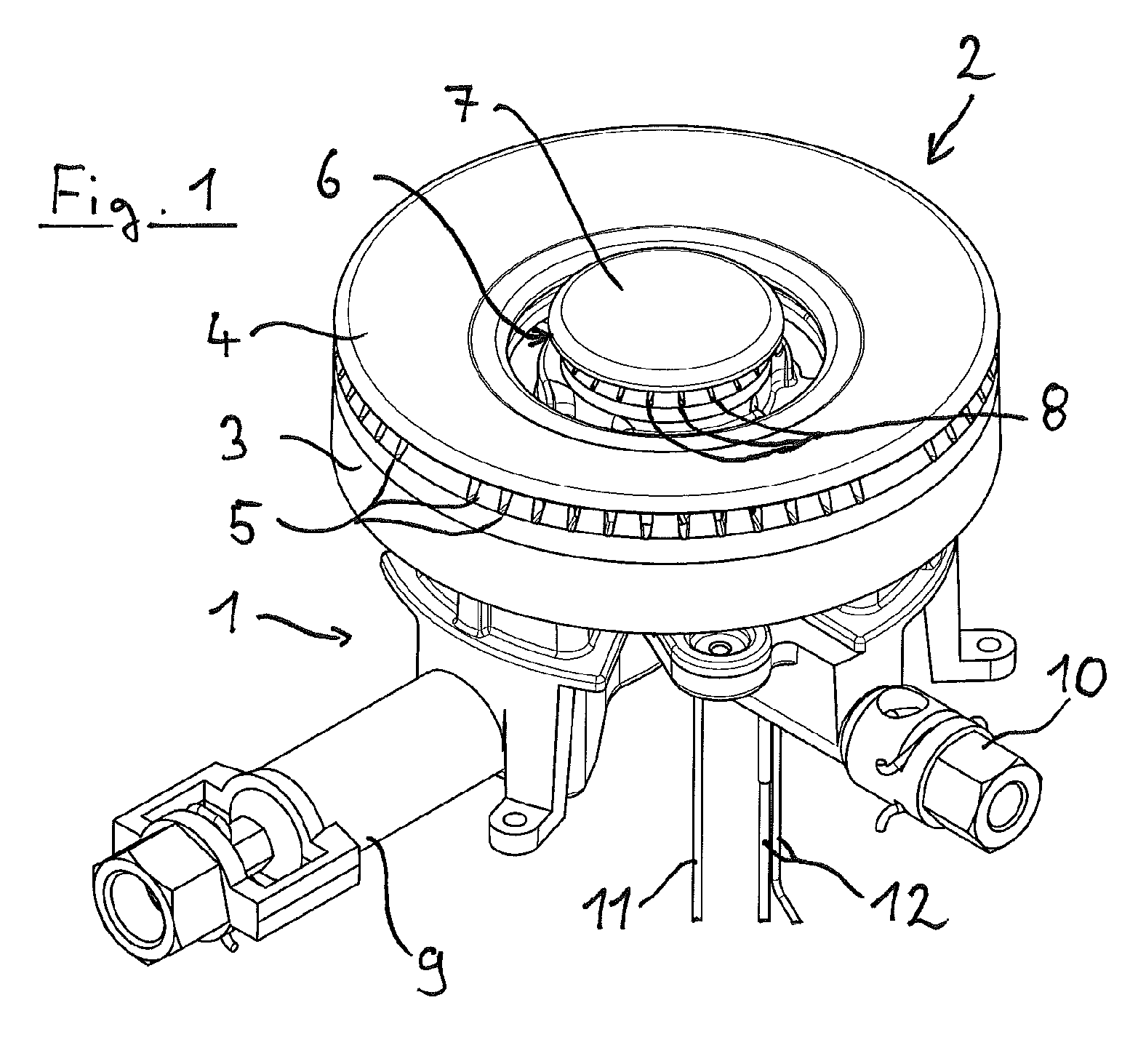
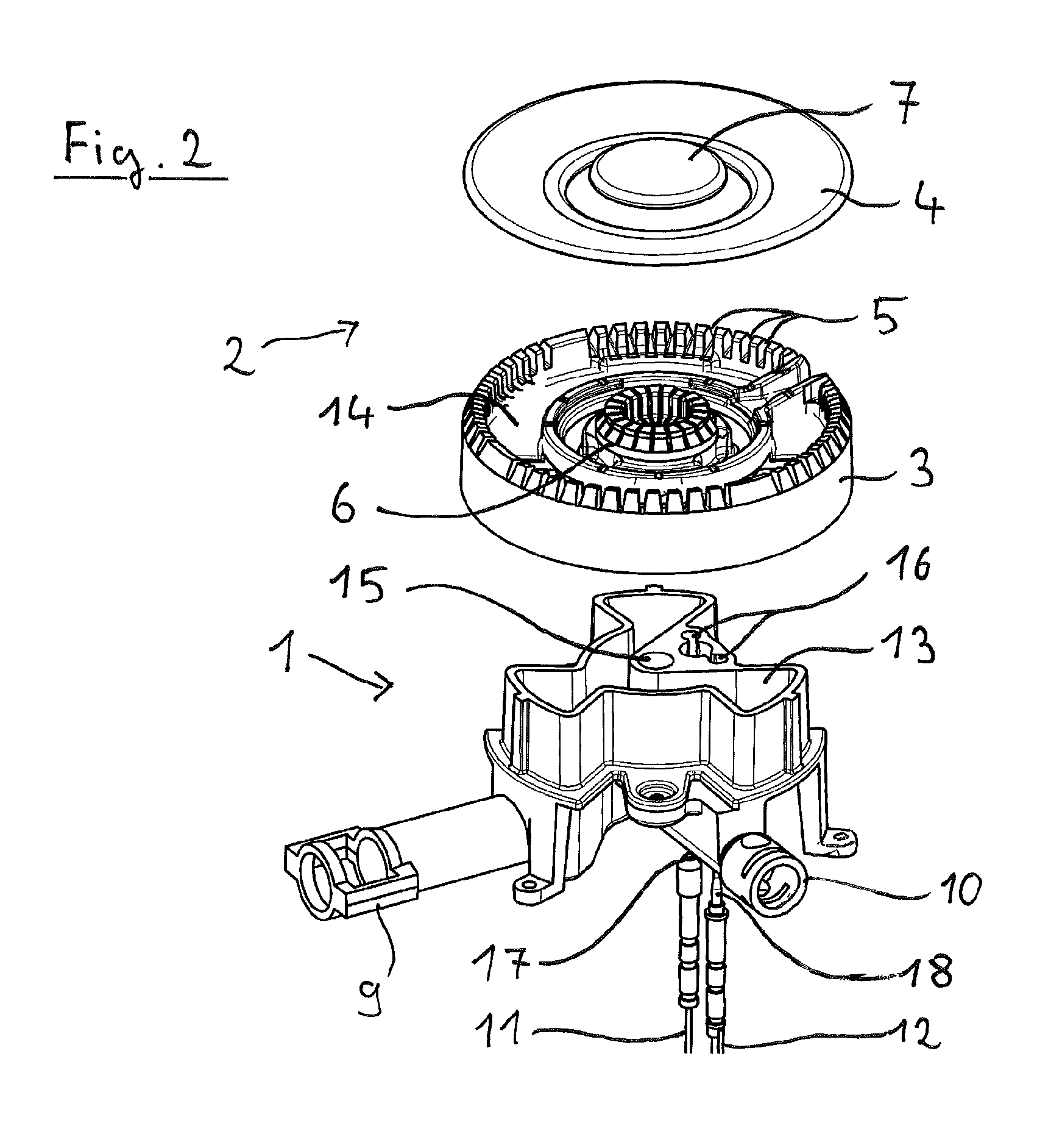
[0028]FIG. 1 shows an exemplary embodiment of an inventive gas burner with a burner lower part 1 and burner upper part 2. Associated with the burner upper part 2 is a burner ring 3 with a burner cover 4 positioned on top. Gas outlet openings 5 are incorporated in the burner ring 3, at which gas flames burn during operation of the gas burner. These gas outlet openings 5 are bounded at the top by the burner cover 4. Located in an inner region of the burner ring 3 is a separate inner burner 6, which is sealed off at the top by an inner burner cover 7. The inner burner 6 also has gas outlet openings 8, at which gas flames burn during operation of the inner burner.

[0029]Associated with the burner lower part 1 is a nozzle injector unit 9, in which the gas provided for combustion is mixed with air components (the so-called primary air). The nozzle injector unit 9 serves to supply the gas outlet openings 5 on the burner ring 3. A further nozzle injector unit 10 is provided to supply the inn...


PUM


Abstract

A gas burner with a burner lower part with a lower gas distribution chamber which is open at the top and a radial secondary air passage to supply secondary air to an inner region of the gas burner, and a burner upper part positioned loosely on the burner lower part and partially closing off the lower gas distribution chamber, and which includes a burner ring, in which an annular upper gas distribution chamber is configured, and which has a gas throughflow opening corresponding to the lower gas distribution chamber and connecting the lower gas distribution chamber to the upper gas distribution chamber.

Description

BACKGROUND OF THE INVENTION[0001]The invention relates to a gas burner with a burner lower part, in which a lower gas distribution chamber, which is open at the top, is configured, with a burner upper part, which can be positioned loosely on the burner lower part and partially closes off the lower gas distribution chamber, and which includes a burner ring, in which an upper gas distribution chamber is configured, and which has a gas throughflow opening corresponding to the lower gas distribution chamber and connecting the lower gas distribution chamber to the upper gas distribution chamber.BRIEF SUMMARY OF THE INVENTION[0002]Gas burners of the above-mentioned type are employed in gas hotplates, for example in gas hobs, which are built into a kitchen worktop, or in free-standing gas cookers. The gas burner is secured to a hob plate, also referred to as a top sheet, generally made of steel, ceramic or hard glass. In this process the burner lower part is inserted from below into an ope...

Claims


Application Information

Patent Timeline
Patent Type & Authority Patents(United States)
IPC IPC(8): F24C3/00
CPCF23D2900/14062F23D14/06
Inventor CADEAU, CHRISTOPHENAUMANN, JORN
Owner BSH BOSCH & SIEMENS HAUSGERAETE GMBH
Why Eureka
Try Eureka