Printhead ink supply system comprising ink pressure regulator

a technology of ink supply system and printhead, which is applied in printing, other printing apparatus, etc., can solve the problems of insufficient de-priming force, clear undesirable flooding of printhead face, and nozzles that can leak ink onto the printhead fa

Inactive Publication Date: 2010-04-27
SILVERBROOK RES PTY LTD +1
View PDF7 Cites 8 Cited by
  • Summary
  • Abstract
  • Description
  • Claims
  • Application Information

AI Technical Summary

Benefits of technology

[0019]an air channel connecting the air inlet and the bubble outlet; anda first ink line providing fluid communication between said ink outlet and an inlet channel of said printhead.Optionally, said ink reservoir is defined by said ink chamber.Optionally, said ink pressure regulator is a replaceable ink cartridge.In a further aspect there is provided an ink supply system, further comprising an ink cartridge defining said ink reservoir, said ink cartridge having an ink supply port in fluid communication with an ink inlet port of said ink chamber.In a further aspect there is provided an ink supply system, further comprising a second ink line providing fluid communication between an outlet channel of said printhead and a return inlet of said ink reservoir, such that said ink supply system is a loop.Optionally, said return inlet comprises an ink filter for filtering returned ink.Optionally, a first pump is positioned in said first ink line upstream of said printhead.Optionally, said first pump is open and idle during printing, such that said pressure regulator determines the hydrostatic pressure of the ink in the printhead during printing.Optionally, a second pump is positioned in said second ink line downstream of said printhead.Optionally, said first and second pumps are independently configurable for priming, depriming, purging and printing operations.Optionally, said bubble outlet is dimensioned such that a hydrostatic pressure of ink in the chamber is at least 10 mm H2O less than atmospheric pressure.Optionally, said bubble outlet has a critical dimension controlling the Laplace pressure of the air bubbles exiting the bubble outlet.Optionally, said bubble outlet is configured as a slot having a length dimension and a width dimension, such that said width dimension controls the Laplace pressure of the air bubbles.Optionally, a width of said slot is less than 200 microns.Optionally, the bubble outlet is positioned for bubbling air bubbles into ink contained in the chamber, each air bubble comprising an air cavity trapped inside a body of ink.In a further aspect there is provided a pressure regulator, further comprising a pressure-release valve for releasing excess pressure in a headspace above ink in said chamber.Optionally, said air channel is bent or tortuous for minimizing ink losses through the air inlet.Optionally, the bubble outlet is positioned for bubbling air bubbles into a headspace above ink contained in the chamber, each air bubble comprising an air bubble trapped inside a film of ink.In a further aspect there is provided a pressure regulator, further comprising a capillary channel in fluid communication with ink contained in the ink chamber, said capillary channel supplying ink from the chamber to the bubble outlet by capillary action.In a second aspect the present invention provides an ink pressure regulator for regulating a hydrostatic pressure of ink supplied to an inkjet printhead, said regulator comprising:
[0024]wherein said bubble outlet is dimensioned to control a Laplace pressure of air bubbles drawn into said ink as result of supplying ink to the printhead, thereby regulating a hydrostatic pressure of the ink.Optionally, said ink chamber is an ink reservoir for a printer.Optionally, said ink chamber has an ink inlet port for fluid communication with an ink reservoir.Optionally, said bubble outlet is dimensioned such that a hydrostatic pressure of ink in the chamber is at least 10 mm H2O less than atmospheric pressure.Optionally, said bubble outlet is dimensioned such that a hydrostatic pressure of ink in the chamber is at least 100 mm H2O less than atmospheric pressure.Optionally, said bubble outlet has a critical dimension controlling the Laplace pressure of the air bubbles exiting the bubble outlet.Optionally, said bubble outlet is configured as a circular opening, such that a radius of said circular opening controls the Laplace pressure of the air bubbles.Optionally, said bubble outlet is configured as a slot having a length dimension and a width dimension, such that said width dimension controls the Laplace pressure of the air bubbles.Optionally, a width of said slot is less than 200 microns.Optionally, each cross-sectional dimension of said air channel is greater than the width of the slot, thereby minimizing flow resistance in the air channel.Optionally, said air channel is bent or tortuous for minimizing ink losses through the air inlet.Optionally, said air channel is dimensioned such that a maximum capillary volume of ink in said channel is less than about 0.1 mL.Optionally, one wall of said chamber comprises an air intake plate, said plate comprising the air inlet, the air channel and the bubble outlet.Optionally, said plate comprises a plurality of laminated layers, said layers cooperating to define the air inlet, the air channel and the bubble outlet.Optionally, said plate comprises:

Problems solved by technology

Printhead face flooding is clearly undesirable in either of these scenarios.
It cannot be strong enough to de-prime the chambers (i.e. suck the ink out of the chambers and back towards the cartridge).
However, if the negative pressure is too weak, the nozzles can leak ink onto the printhead face, especially if the printhead is jolted.
Aside from these two catastrophic events requiring some form of remediation (e.g. printhead maintenance or re-priming), a sub-optimal hydrostatic ink pressure will typically cause an array of image defects during printing, with an appreciable loss of print quality.
Further, the requirement of an internal biasing means in a flexible bag presents significant manufacturing difficulties.
However, ink cartridges comprising foam inserts are generally unsuitable for high speed printing (e.g. print speeds of one page every 1-2 seconds) using the Applicant's pagewidth printheads, which print at up to 1600 dpi.
The hydraulic drag caused by the foam insert can starve the nozzles and retard the chamber refill rate.
Further, accurate pressure control requires equally accurate control over the internal void dimensions, which is difficult to achieved by the stochastically formed void structures of most foam materials.
Accordingly, porous foam inserts are not considered to be a viable means for controlling ink pressure at high ink flow rates.
However, this type of mechanical pressure regulator has the drawback of requiring extremely fine manufacturing tolerances for a spring, which opens and closes the diaphragm in response to fluctuations in ink pressure upstream and downstream of the diaphragm.
In practice, this mechanical system of pressure control makes it difficult to implement in an ink supply system required to maintain a constant negative hydrostatic ink pressure within a relatively narrow pressure range.

Method used


Image

  • Printhead ink supply system comprising ink pressure regulator
  • Printhead ink supply system comprising ink pressure regulator
  • Printhead ink supply system comprising ink pressure regulator

Examples


Embodiment Construction

Pressure Regulator With Circular Bubble Outlet

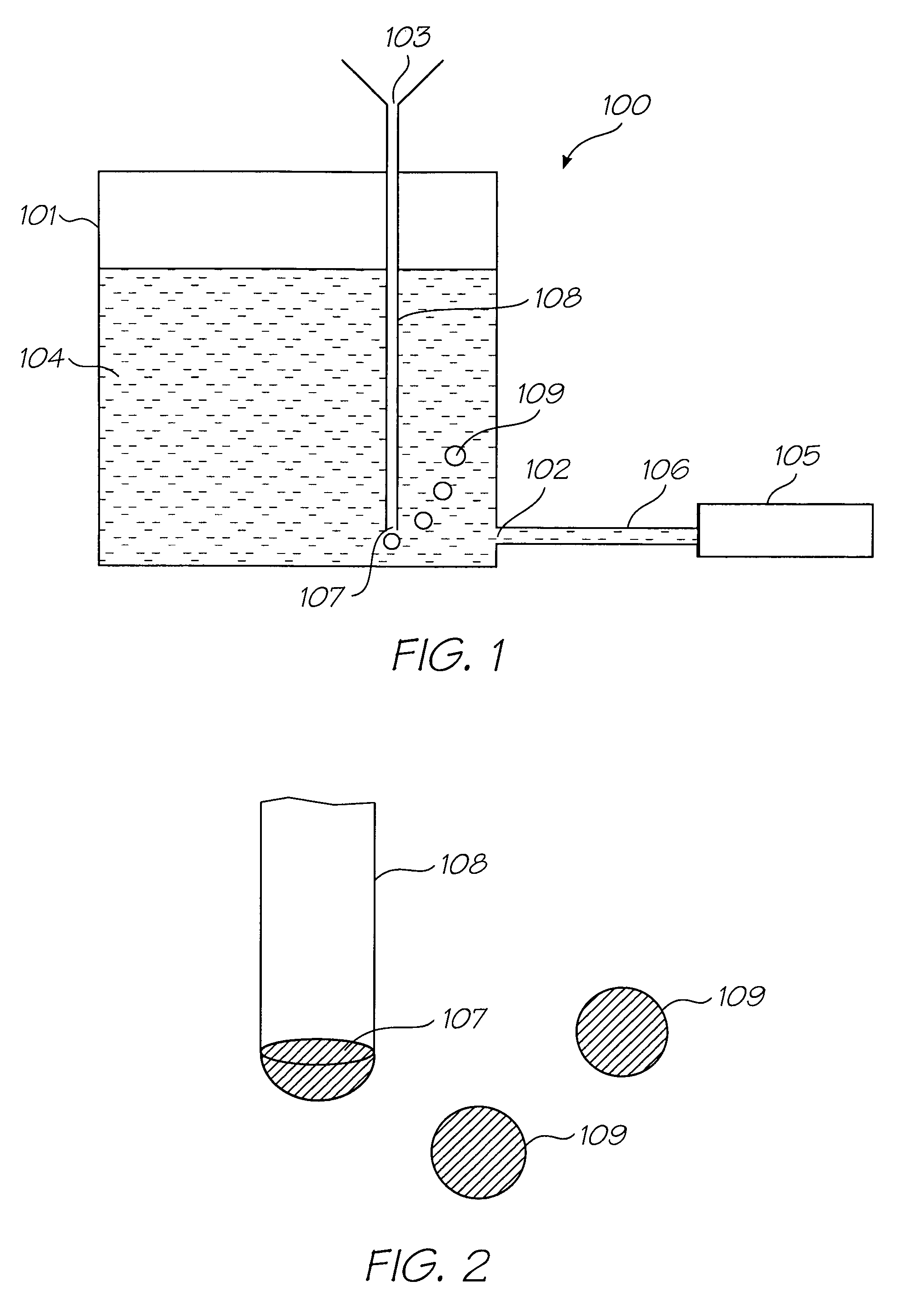
[0065]FIG. 1 shows the simplest form of the present invention, for the purposes of explaining the basic operating principle of the pressure regulator. In FIG. 1, there is shown a pressure regulator 100 comprising an ink chamber 101 having an ink outlet 102 and air inlet 103. The ink chamber 101 is otherwise sealed. The ink outlet 102 is for supplying ink 104 to a printhead 105 via an ink line 106. A bubble outlet 107 is connected to the air inlet 103 via an air channel 108.

[0066]When ink 104 is drawn from the ink chamber 101 by the printhead 105, the displaced volume of ink must be balanced with an equivalent volume of air, which is drawn into the chamber via the air inlet 103. The bubble outlet 107, which is positioned below the level of ink, ensures that the air enters the chamber 101 in the form of air bubbles 109. The dimensions of the bubble outlet 107 determine the size of the air bubbles 109 entering the chamber 101.

[0067]As shown...


PUM


Abstract

A printhead ink supply system is provided. The system comprises an inkjet printhead; an ink reservoir; an ink pressure regulator and an ink line connecting the printhead and the regulator. The ink pressure regulator regulates a hydrostatic pressure of ink supplied to the printhead and comprises an ink chamber having an ink outlet; an air inlet open to atmosphere; a bubble outlet for bubbling air bubbles into the chamber and an air channel connecting the air inlet and the bubble outlet. Each air bubble comprises an air cavity trapped inside a film or a body of ink and the bubble outlet is dimensioned to control a Laplace pressure of air bubbles drawn into the chamber as result of supplying ink to the printhead.

Description

FIELD OF THE INVENTION[0001]The present invention relates to a pressure regulator for an inkjet printer. It has been developed primarily for generating a negative hydrostatic pressure in an ink supply system supplying ink to printhead nozzles.CO-PENDING APPLICATIONS[0002]The following applications have been filed by the Applicant simultaneously with the present application:[0003]11 / 640356 11 / 640358 11 / 640359 11 / 640360 11 / 640355[0004]The disclosures of these co-pending applications are incorporated herein by reference.CROSS REFERENCES TO RELATED APPLICATIONS[0005]Various methods, systems and apparatus relating to the present invention are disclosed in the following US Patents / Patent Applications filed by the applicant or assignee of the present invention:[0006]09 / 517,5396,566,8586,331,9466,246,9706,442,52509 / 517,38409 / 505,9516,374,35409 / 517,60809 / 505,1476,757,8326,334,1906,745,33109 / 517,54110 / 203,55910 / 203,5607,093,13910 / 636,26310 / 636,28310 / 866,60810 / 902,88910 / 902,83310 / 940,65310 / 942...

Claims


Application Information

Patent Timeline
Patent Type & Authority Patents(United States)
IPC IPC(8): B41J29/38B41J2/175
CPCB41J2/17513B41J2/19B41J2/17556
Inventor MORGAN, JOHN DOUGLAS PETERWANG, MIAOMCAULIFFE, PATRICK JOHNWORBOYS, DAVID JOHNSILVERBROOK, KIA
Owner SILVERBROOK RES PTY LTD
Why Eureka
Try Eureka