High capacity water diversion conduit

a technology of high-capacity water diversion conduits and conduits, which is applied in marine site engineering, applications, lighting and heating equipment, etc., can solve the problems of limited flume flow capacity, significant downstream environmental impact, and inability to provide the required capacity economically

Inactive Publication Date: 2010-09-21
MCBRIDE TODD
View PDF24 Cites 6 Cited by
  • Summary
  • Abstract
  • Description
  • Claims
  • Application Information

AI Technical Summary

Benefits of technology

[0018]It is an object of the present invention to obviate or mitigate at least one disadvantage of previous stream diversion methods and fluid diversion conduits.
[0020]The conduit may be constructed from any suitable material, such as steel pipe, or another rigid or flexible material. Moreover, the conduit may be constructed from a combination of rigid and flexible materials. The internal surface of the conduit may be coated with a substance that minimizes skin friction flow resistance.
[0030]In accordance with a third aspect of the invention, there is provided a method for increasing the flow capacity of a fluid diversion conduit comprising the step of: integrating a hydraulic flow diffuser segment within an outflow end of the conduit, the hydraulic flow diffuser segment comprising a length of tubing that gradually increases in cross sectional area in the direction of flow so as to slow the flow of fluid and recover dynamic head prior to discharge of water from the outflow end of the conduit.
[0036]The present fluid diversion conduit may be made of lightweight material so as to be simply and easily transported and manipulated.

Problems solved by technology

If the diversion system cannot handle such flow volumes, a catastrophic flooding of the construction site may occur, with significant downstream environmental impacts.
The flow capacity of the flume is limited by the hydraulic head difference between the water levels behind the cofferdams.
In streams where very large flow volumes must be diverted, the required capacity cannot be provided economically with the large pipe flumes discussed above.
These structures are necessarily huge, heavy, and expensive to build.
They are also expensive to transport and install.
Another disadvantage to the large size of these superflumes is the resulting limitation of access to the streambed for excavation and underground pipe installation.
Further, the flow in a box channel “superflume” is generally limited by inlet conditions.
Since the total force on the dam increases approximately with the inlet depth squared, this becomes an expensive undertaking as well.
The high discharge flow velocity out of flumes generally poses an erosion problem in the downstream bed.
This increases the environmental impacts to the stream and also increases the probability that a stream freshet will occur during the isolate and bypass operation.
Large pipeline projects, involving the crossing of hundreds of streams, are restricted to using “isolate and bypass” construction methods.

Method used


Image

  • High capacity water diversion conduit
  • High capacity water diversion conduit
  • High capacity water diversion conduit

Examples


Embodiment Construction

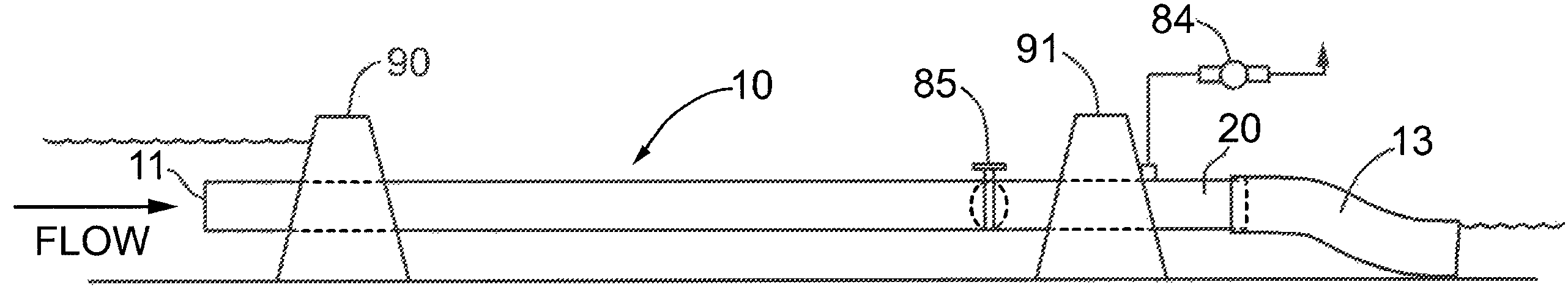
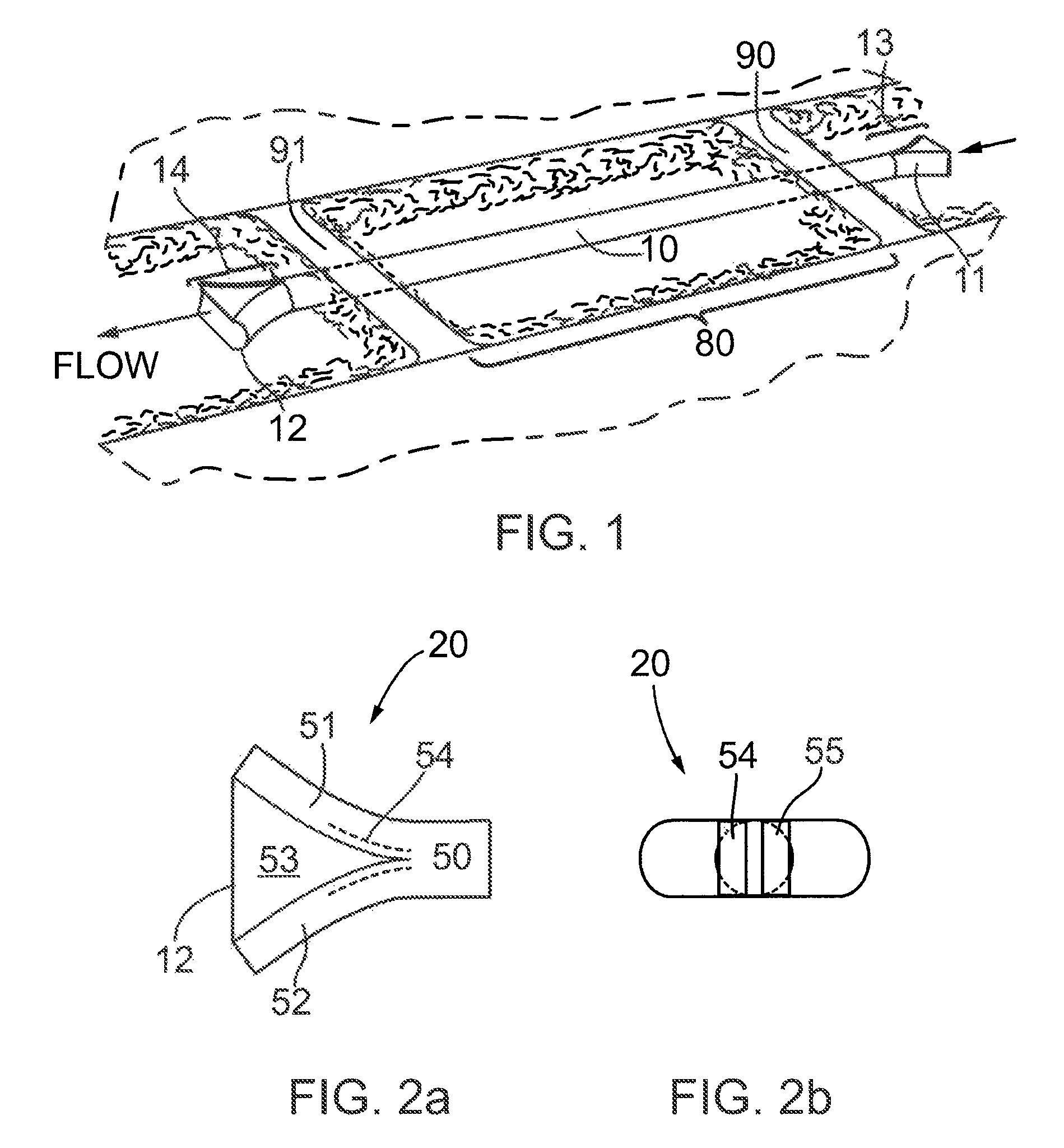
[0044]Generally, the present invention provides a fluid diversion conduit for temporarily diverting stream flow, for example to provide construction access to a portion of the streambed. With reference to FIG. 1, an upstream cofferdam 90 generates a head of hydraulic pressure upstream of the cofferdam 90, initiating flow through the diversion conduit 10. Stream flow therefore enters conduit 10 at the conduit inlet 11, is conveyed past the diversion site 80 and through a downstream cofferdam 91, where flow is returned to the natural streambed upon exiting the conduit 10 at outlet 12.

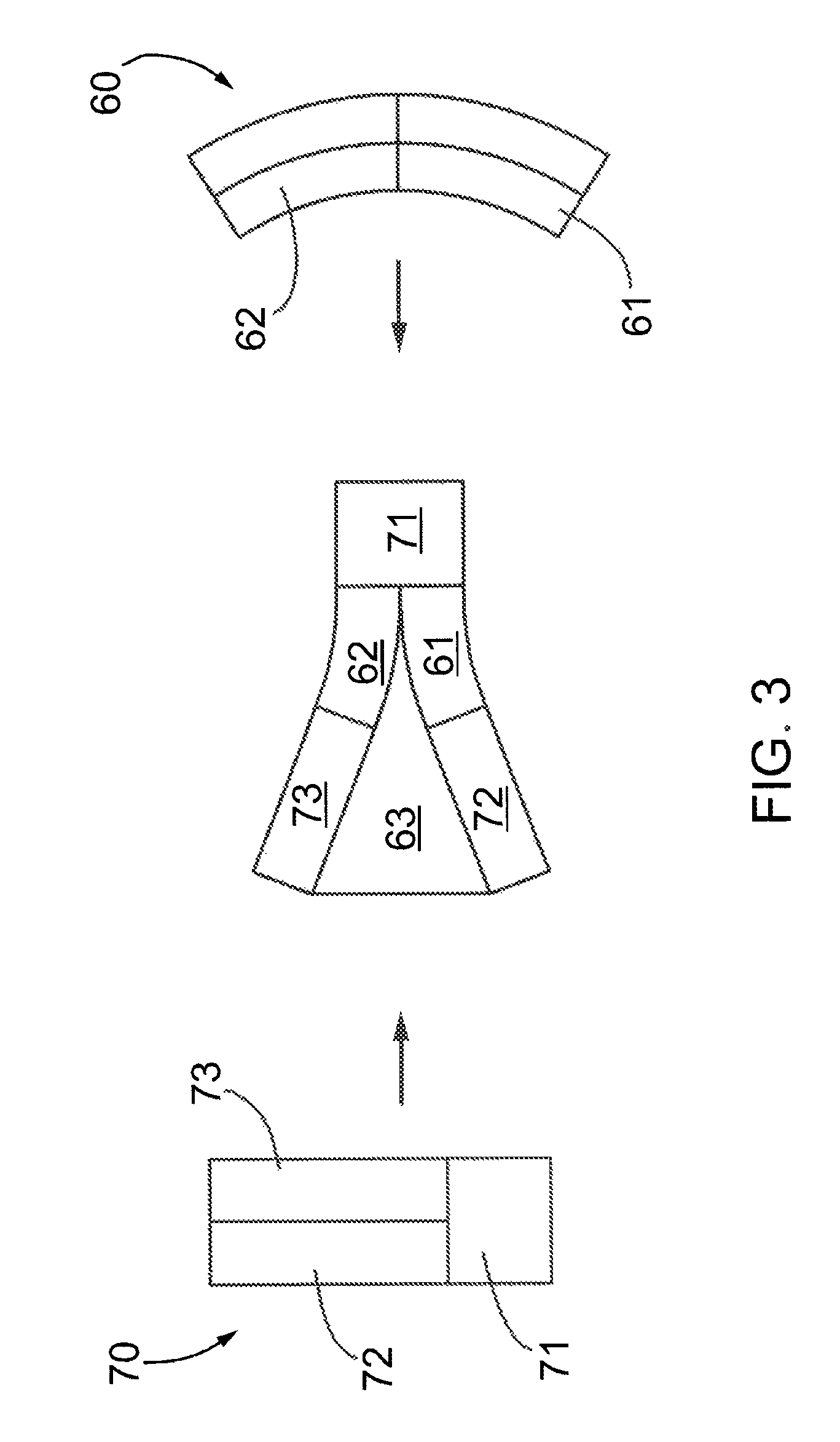
[0045]Generally, achieving higher hydraulic capacity in a flowing system is accomplished by reducing the hydraulic losses of the system. The types of hydraulic loss typically experienced in water bypass ducts include: inlet loss; skin friction loss; and exit loss. The inlet loss may be minimized by a smoothly contoured inlet configuration. This practice is widely used in culverts and other drainage system...


PUM


Abstract

A fluid diversion conduit is described for diverting the flow of fluid, and particularly for diverting water from a stream to a discharge location. The discharge end of the duct has a segment of gradually enlarging cross sectional area, forming a hydraulic flow diffuser. Water flow through this segment is thereby slowed as the flow area increases, and most of the dynamic head of the water flow is recovered, improving flow capacity of the conduit. The rate of flow through the conduit may be monitored and controlled to achieve streamline flow in the diffuser section, and to prevent air from entering the diffuser section. Air entering the conduit may be expelled or otherwise displaced from the conduit.

Description

CROSS-REFERENCE TO RELATED APPLICATIONS[0001]This application claims priority from Canadian Patent Application No. 2,629,539 filed on Apr. 23, 2008, the entire contents of which are incorporated herein by reference.FIELD OF THE INVENTION[0002]The present invention relates generally to fluid diversion conduits. More particularly, the present invention relates to a conduit with reduced hydraulic resistance and improved flow capacity for use in diverting stream flow during construction operations.BACKGROUND OF THE INVENTION[0003]It is often necessary to divert a stream from a section of its natural streambed during various construction projects, such as road, bridge, or buried pipeline crossing construction. The stream diversion is required to avoid disrupting the stream flow and releasing turbidity into the downstream waters. A typical construction activity that requires this “isolate and bypass” method is the installation of a buried pipeline crossing under the streambed. In order to...

Claims


Application Information

Patent Timeline
Patent Type & Authority Patents(United States)
IPC IPC(8): F15D1/04
CPCF15D1/02
Inventor MCBRIDE, TODD
Owner MCBRIDE TODD
Why Eureka
Try Eureka