Retractable gas turbine inlet coils

a chiller coil and gas turbine technology, applied in the field of gas turbines, can solve the problems of large inlet filter houses, inability to reduce gas turbine efficiency and output, and inability to achieve the effect of reducing resistance to flow and maximizing resistance to flow

Active Publication Date: 2013-02-28
GENERAL ELECTRIC CO
View PDF0 Cites 9 Cited by
  • Summary
  • Abstract
  • Description
  • Claims
  • Application Information

AI Technical Summary

Benefits of technology

[0007]In a first exemplary but nonlimiting embodiment, the present invention provides a gas turbine inlet heat exchange coil assembly comprising a gas turbine inlet housing formed to include an inlet and an outlet and a flow path therebetween; a plurality of adjacent coils located in proximity to the inlet, and moveable between a closed operative position where the coils are aligned substantially in a plane so as to maximize resistance to flow along the flow path, and an open inoperative position where the coils are individually rotated substantially 90° such that the heat exchange coils lie in individual, parallel planes so as to minimize resistance to flow along the flow path.
[0008]In another exemplary but nonlimiting aspect, the invention provides a gas turbine inlet compressor chiller coil assembly comprising a gas turbine inlet housing formed to include an inlet and an outlet and a flow path therebetween; a plurality of adjacent, substantially vertically-oriented chiller coils located in proximity to the inlet, and moveable between a closed operative position where the chiller coils are aligned substantially in a vertical plane so as to maximize resistance to flow along the flow path, and an open inoperative position where the chiller coils are individually rotated substantially 90° such that the heat exchange coils lie in individual, substantially parallel vertical planes so as to minimize resistance to the air flow along the flow path; and at least one actuator for moving the plurality of adjacent, substantially vertically-oriented the coils between the closed operative position and the open inoperative position.
[0009]In still another exemplary but nonlimiting aspect, the invention provides a method of managing a power augmentation system located in an inlet filter house to a gas turbine comprising aligning individual heat exchange coils of a chiller unit so as to be substantially aligned within a substantially vertical plane when the power augmentation system is operating; and rotating the individual heat exchange coils of a chiller unit so as to be oriented in plural substantially parallel planes and thus minimizing flow resistance, when the power augmentation system is not operating.

Problems solved by technology

The use of an inlet-chiller-type power augmentation system utilizing coils, however, adds resistance to the air flow entering the compressor, creating an undesirable pressure drop in the inlet system.
Thus, while the power augmentation system increases the gas turbine output and efficiency when operating at the desired ambient conditions, it has been determined that when the power augmentation system is not operating, the additional pressure drop that the system adds to the air inlet stream reduces the gas turbine efficiency and output.
This approach, however, requires larger inlet filter houses and attendant higher costs.

Method used


Image

  • Retractable gas turbine inlet coils
  • Retractable gas turbine inlet coils
  • Retractable gas turbine inlet coils

Examples


Embodiment Construction

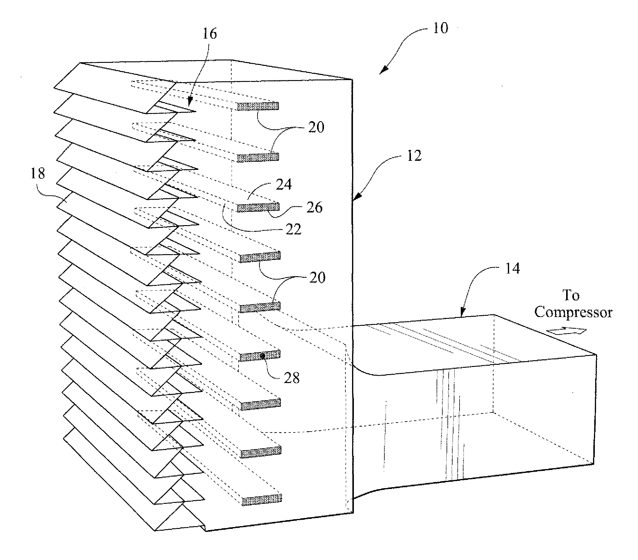
[0016]With reference initially to FIG. 1, a inlet filter house or housing 10 is shown to include a first substantially vertically-oriented duct section or filter house envelope 12 joined to a second substantially horizontally-oriented inlet duct section 14 that leads to the turbine compressor (not shown). The invention is not limited, however, to any particular inlet / duct configuration. The filter house envelope 12 is typically a box-like structure with a number of filters (not shown) positioned at the inlet 16 to limit the intake of dust or debris into the gas turbine engine. A plurality of substantially horizontally-oriented and vertically-aligned louvers 18 guide the inlet air into the filter house.

[0017]Also positioned within the envelope 12, downstream and adjacent the filters, there is a power augmentation system which may comprise a vertically-aligned array of porous inlet heat exchanger or chiller coils 20, lying directly in the inlet air flow path. As will be described in g...


PUM

PropertyMeasurementUnit
resistanceaaaaaaaaaa
flow resistanceaaaaaaaaaa
temperatureaaaaaaaaaa

Abstract

A gas turbine inlet heat exchange coil assembly includes a gas turbine inlet housing formed to include an inlet and an outlet and a flow path therebetween. A plurality of adjacent coils are located in proximity to the inlet, and moveable between a closed operative position where the coils are aligned substantially in a plane so as to maximize resistance to flow along the flow path, and an open inoperative position where said coils are individually rotated substantially 90° such that the coils lie in individual, parallel planes so as to minimize resistance to flow along the flow path.

Description

BACKGROUND[0001]The present application relates generally to gas turbines and more particularly to a retractable chiller coil arrangement in gas turbine inlet filter house.BACKGROUND OF THE INVENTION[0002]Gas turbine engines typically include a compressor for compressing incoming air, a combustor for mixing fuel with the compressed air and igniting the fuel / air mixture to produce a high temperature gas stream, and a turbine section that is driven by the high temperature gas stream. It is generally accepted that lowering the temperature of the inlet air entering the compressor results in an increased power output, and there are known methods for reducing the air inlet temperature to the engine in so-called power augmentation systems. A power augmentation system may include a chiller coil in the filter house, along with evaporative coolers that reduce the temperature of the inlet air stream. Examples of power augmentation arrangements are described in, for example, U.S. Pat. No. 7,007...

Claims


Application Information

Patent Timeline
Patent Type & Authority Applications(United States)
IPC IPC(8): F02C7/04B23P17/00F02C7/00
CPCY10T29/49229F02C7/143
Inventor LAFONTAINE, ERIC MILTONSULLIVAN, MICHAEL ADELBERTVU, HUONG VANDESAI, BHALCHANDRA ARUNCOURNOYER, MARK ANDREW
Owner GENERAL ELECTRIC CO
Why Eureka
Try Eureka